
using led as a light sensor
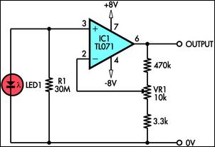
The circuit operates on the principle that when an LED is illuminated, it generates a small voltage due to the photovoltaic effect. This phenomenon occurs when photons strike the semiconductor material of the LED, causing electron-hole pairs to form and generating a measurable voltage. The generated voltage can be influenced by the intensity and wavelength of the incident light, making this configuration suitable for various light-sensing applications.
In the described circuit, the red LED serves as the light sensor, producing a voltage output that varies with light exposure. The TL071 operational amplifier, known for its high input impedance and low output impedance, is critical for ensuring that the signal from the LED is not adversely affected by loading effects. The operational amplifier is configured as a non-inverting amplifier, which allows for both amplification and buffering of the signal.
The circuit's design should include appropriate biasing and gain settings for the TL071 to optimize performance. A feedback resistor network can be implemented to set the gain, while ensuring that the input impedance remains sufficiently high to accommodate the LED's output without drawing significant current. Additionally, bypass capacitors may be added to the power supply lines of the op-amp to minimize noise and improve stability.
This configuration is particularly useful in applications where cost and space are constraints, such as in portable devices or low-power sensors. The ability to discriminate colors based on the LED's characteristics further enhances the versatility of this circuit in various optical sensing applications.This circuit shows how to use an ordinary LED as a light sensor. It makes use of the photovoltaic voltage developed across the LED when it is exposed to light. LEDs are cheaper than photodiodes and come with a built-in filter, which is useful when the application involves colour discrimination. The photo-voltage of a red LED (its bandgap voltage) is typically about 2V. The source impedance of this voltage is about 800M? in daylight, rising to infinity in darkness. A TL071 JFET input op amp is used to amplify and buffer this extremely high impedance signal.. 🔗 External reference
Related Circuits
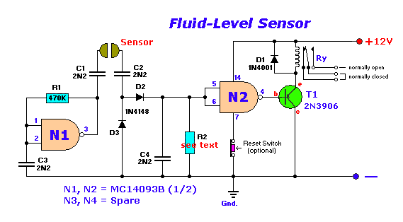
The circuit diagram presented illustrates the MC14093B Fluid Level Sensor Circuit. It is characterized by its compact and simple design, utilizing a single-chip configuration suitable for a wide range of applications. The MC14093B is a CMOS quad two-input NAND gate...
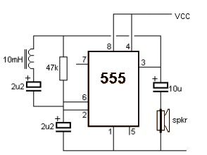
A simple metal detector circuit can be implemented using a 555 timer chip. The schematic diagram illustrates that this project requires only a few external electronic components. The metal detector circuit utilizing a 555 timer operates in astable mode, generating...

The circuit is designed to seek light, allowing a robot to follow a flashlight in a dark room. Two photocells are used to determine the direction of the robot's movement. Each photocell is connected to an operational amplifier configured...

Up to 100 lights, LEDs, or optocoupler triac circuits can be sequentially activated by this circuit. One (U1) 4017 decodes and sequences 10 LEDs, whose common anode is returned through a second (U2) CD4017, which counts at one-tenth of...

This is an intriguing 555 timer circuit designed to entertain and engage individuals while studying electronics in educational settings. Commonly referred to as a clap switch circuit, it operates as a sound-controlled flip-flop. This sound-controlled light can also function...

This is a simple frequency counter based on the microcontroller PIC16F84. Its maximum operating frequency is approximately 30 MHz, with a resolution of 10 Hz and low current consumption of 15 mA. The assembly process is straightforward. The device...