
Headphone Amplifier circuit
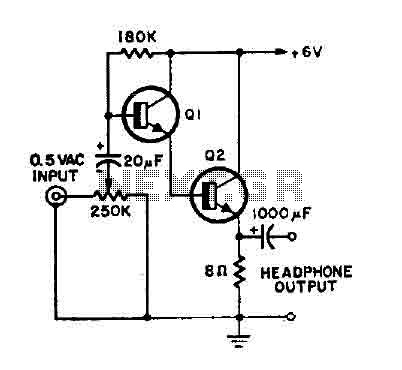
The headphone amplifier circuit serves to boost audio signals to a level suitable for driving headphones. It typically consists of an NPN transistor, which functions as the main amplification component. The choice of the NPN transistor is flexible, allowing for various models based on availability and desired specifications.
The circuit operates with a 9V battery, providing sufficient voltage to ensure optimal performance. The input audio signal can be fed into the base of the transistor, where it is amplified. The collector of the transistor is connected to the power supply, while the emitter connects to the output, which leads to the headphones.
To optimize performance, it is advisable to include a biasing resistor at the base to set the operating point of the transistor. Additionally, coupling capacitors can be used at the input and output to block any DC offset, ensuring that only the AC audio signal is passed through to the headphones.
The output impedance should be matched appropriately to the headphones being used to maximize sound quality and prevent distortion. Overall, this simple headphone amplifier circuit is an effective solution for enhancing audio signals and can be easily constructed with basic electronic components.This is a simple headphone amplifier. You can use any NPN transistor. You can drive this circuit with a 9V batery. 🔗 External reference
Related Circuits
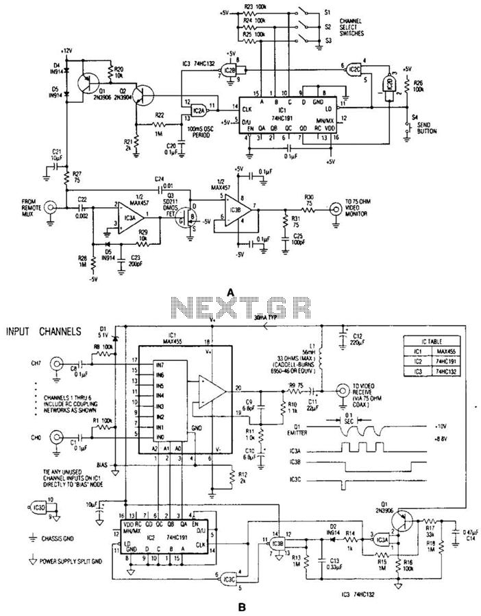
In the video system illustrated in Figures A and R, a single coaxial cable transmits power to a remote location, selects one of eight video channels, and returns the selected signal. This system can choose from several remote surveillance...
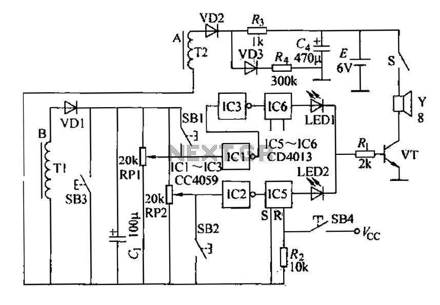
A and B are oxygen electromechanical motors operating in a two-phase and three-phase power system. Tl and T2 are wound around the exterior of two current sensing coils. Under normal power supply conditions, Tl and T2 connect to a...
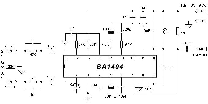
The BA1404 FM stereo modulator IC includes all the necessary components to design a simple, high-efficiency stereo transmitter circuit. It features a stereo modulator that generates composite stereo signals, an FM modulator for creating FM signals, and an RF...
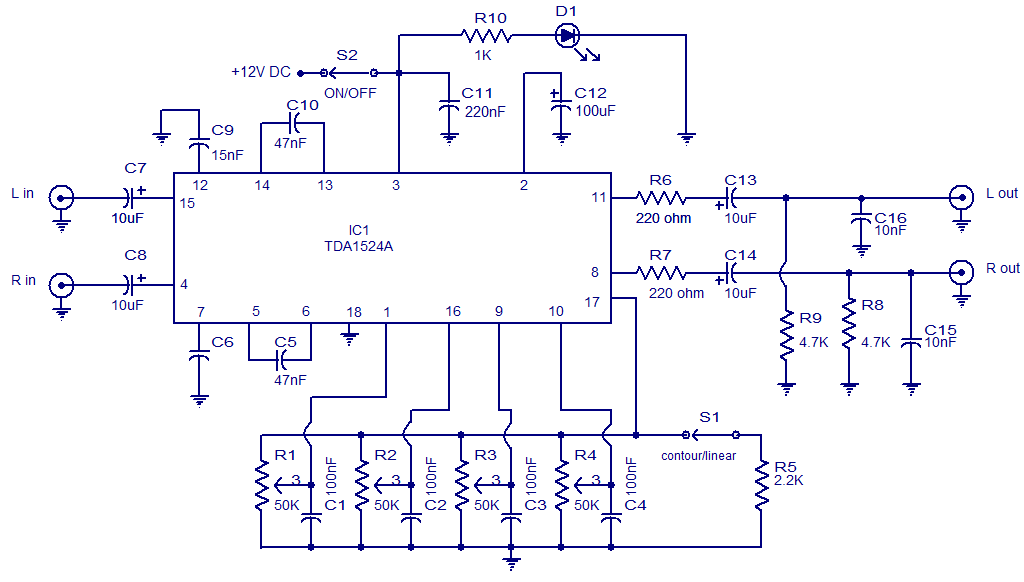
The following circuit illustrates the TDA1524 IC Stereo Preamplifier Circuit Diagram. Features include the ability to control volume, balance, and bass. The TDA1524 is a highly integrated stereo preamplifier IC designed for audio applications. This circuit configuration allows for the...
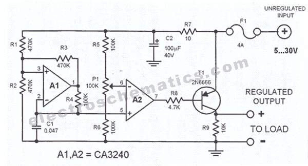
This circuit regulates a DC power output and has a wide range of applications. It can be utilized to control the speed of a motor, a pump, a toy train, or the brightness of an LED or lamp. Essentially,...
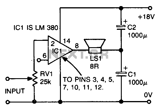
The ground side of the speaker is connected to the junction of two equal high-value capacitors (1000 µF is typical) across the supply. The amplifier output voltage will be Vs/2, and the voltage across CI (if CI and C2...
Warning: include(partials/cookie-banner.php): Failed to open stream: Permission denied in /var/www/html/nextgr/view-circuit.php on line 713
Warning: include(): Failed opening 'partials/cookie-banner.php' for inclusion (include_path='.:/usr/share/php') in /var/www/html/nextgr/view-circuit.php on line 713