
magnetic switch activated alarm
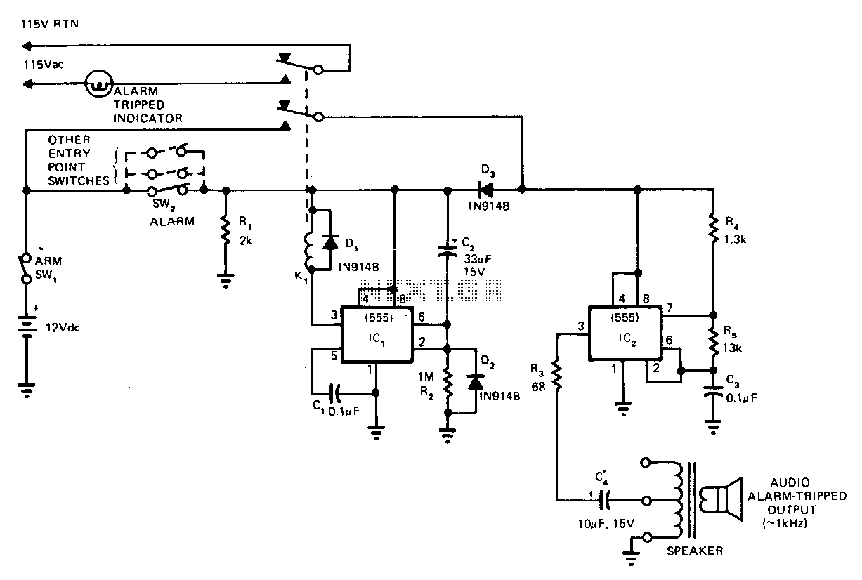
The circuit design comprises two main functional blocks: the alarm generation circuit and the control or input section. The right section, responsible for the alarm, typically includes a sound-generating component, such as a piezoelectric buzzer or a small speaker. This component can be activated by a signal from the left section, which may include switches, sensors, or other input devices.
The left section may incorporate a simple control mechanism, such as a push button or a motion sensor, which triggers the alarm when a specific condition is met. For instance, if a motion sensor detects movement, it sends a signal to the alarm circuit, causing the buzzer to emit a loud sound.
Power supply considerations are essential for both sections. A suitable voltage regulator may be implemented to ensure that the components operate within their specified voltage ranges. Additionally, decoupling capacitors can be used to filter out noise from the power supply, ensuring stable operation of the circuit.
The interconnection between the two sections can be achieved using jumper wires on the breadboard, allowing for flexibility in the circuit layout. Proper labeling and organization of components on the breadboard will facilitate troubleshooting and modifications.
Overall, this circuit can serve various applications, such as security systems, alert mechanisms, or educational projects, demonstrating fundamental principles of electronics and circuit design.Hello, I assembled a circuit on a breadboard which is separated in 2 parts: the right part is for generating an alarm which wails. the left part is.. 🔗 External reference
Related Circuits
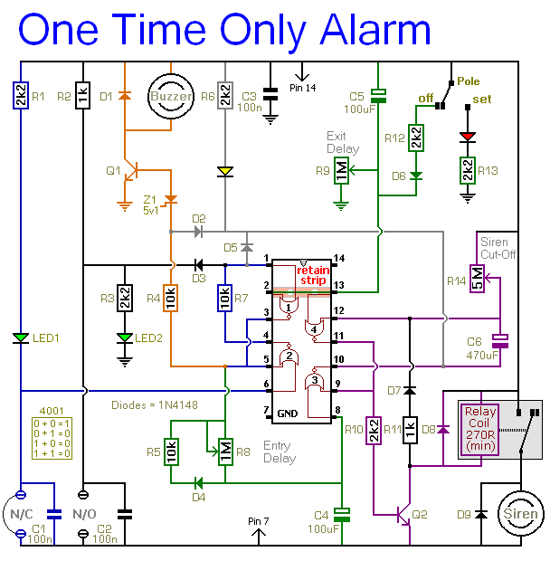
This alarm is designed to activate its siren only once. When the alarm is triggered, the siren will sound for a predetermined duration before automatically turning off and remaining inactive. The alarm system features a single zone with independently...
The thermistor utilized has a resistance of 15 kΩ at 25 degrees Celsius and 45 kΩ at 0 degrees Celsius. A suitable bead-type thermistor can be found in the Maplin catalog. The 100 kΩ potentiometer enables this circuit to...
This circuit cannot be shut off for 10 to 60 seconds, even if the trip condition is immediately removed. It draws no standby power from the battery and is self-resetting. The described circuit operates under a delay mechanism that...
The objective is to enhance information transmission through the distribution of articles. Please contact us via email at [email protected] within 15 days if there are any issues related to article content, copyright, or other concerns. Prompt deletion will occur...
The core component of this heat-sensitive switch is the LM35 integrated circuit (IC1), which functions as a linear temperature sensor and temperature-to-voltage converter. This converter delivers an output signal that is accurately linear and directly proportional in millivolts across...

Utilize the call sheet to touch the electrical threshold M, which causes the E lamp to light up. When the same interval subparagraph is triggered, the lights will automatically turn off. A voltage regulator rectifier circuit is formed using...