
Metal detector circuit diagram 5
The metal detector circuit is designed to detect metallic objects by employing an oscillator to generate a frequency signal that varies in response to the presence of metal. The inductor (L) and capacitor (C1) form a resonant circuit that oscillates at a specific frequency. The sensor switch integrated circuit (IC1), specifically the TDA0161D, houses essential components such as the oscillator, detector, and comparator. This integrated circuit plays a crucial role in processing the signals and determining whether a metallic object is present.
Upon detection of metal, the output from IC1 triggers the sound-light alarm circuit, which is built around the CD4001 integrated circuit containing four NOR gates (IC2). The output from the detector is fed into these NOR gates, which can be configured to activate the alarm system. The sound-light alarm circuit includes a high-brightness light-emitting diode (VL) that visually indicates detection and a speaker (BL) that emits audible alerts.
The resistors (R1 to R6) are selected as 1/4W carbon film types, ensuring stability and reliability in the circuit. Capacitors (C1 to C4) are chosen as ceramic capacitors, known for their low losses and excellent frequency characteristics, which are vital for maintaining the performance of the oscillator. The choice of a 5mm high-brightness LED ensures that the visual alarm is easily noticeable, even in bright environments.
The use of an S9013 or C8050 silicon NPN transistor allows for effective switching capabilities within the circuit, facilitating the control of the alarm components based on the input signal from the sensor switch. Overall, the design of the metal detector circuit integrates these components in a cohesive manner to provide a reliable and efficient means of detecting metallic objects and alerting the user through both sound and light signals.The metal detector circuit consists of oscillator and sound-light alarm circuit, and the circuit is shown as the chart. Oscillator circuit consists of inductor L, capacitor C1, sensor switch integrated circuit IC1 (includes oscillator, detector and comparator circuit, etc.
) and the peripheral components. Sound-light alarm circuit consists of four NOR gate integrated circuit IC2 (Dl ~ D4) and the light-emitting diode VL, speaker BL and other components. R1 ~ R6 select 1/4W carbon film resistors. C1 ~ C4 select ceramic capacitors. VL selects 5mm high-brightness light-emitting diode. V uses S9013 or C8050 silicon NPN transistor. IC1 uses TDA0161D sensor switch integrated circuit; IC2 selects CD4001 four NOR gate integrated circuit.
🔗 External reference
Related Circuits

The circuit illustrated in the figure features an automatic voltage regulator (T) that utilizes a servo motor to ensure a constant output voltage. The transistors used are VT1 and VT2 (3DK9C, with a range of 65 to 85) and...
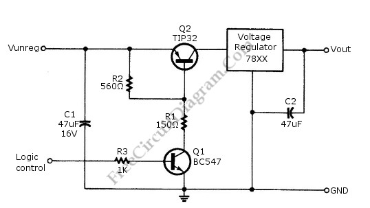
Logic power control of an analog regulator can be useful in applications where a digital circuit or controller needs to manage a power source, such as in EEPROM programmers or other power control systems. This circuit provides ON-OFF control...
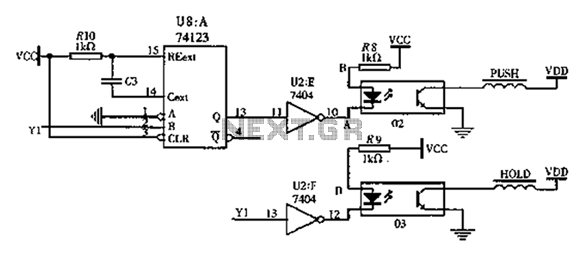
The FIG switching solenoid driver circuit utilizes the 74123 device chip (U8) and solid-state relays (02, 03). The switching electromagnet coil is referred to as the PUSH coil, while the HOL is maintained at a power supply voltage (VDD)...
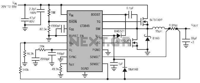
Burst Mode operation maintains high efficiency at light loads by reducing IC quiescent current to 120 µA. Light load efficiency is also improved with the reverse inductor current inhibit function, which supports discontinuous operation. Additional features include an adjustable...
Construct a Wien bridge oscillator that operates at 2.1 kHz and can be activated by a transistor. The inclusion of a transistor switch in the circuit allows for control of the oscillator's operation from a PIC microcontroller. However, during...
This circuit features a micro vibration sensor, a trigger delay circuit, and a control circuit, as illustrated in the accompanying figure. The micro vibration sensor comprises a vibration sensing device and a high power amplifier circuit, enabling it to...