
Mains Powered White LED Lamp
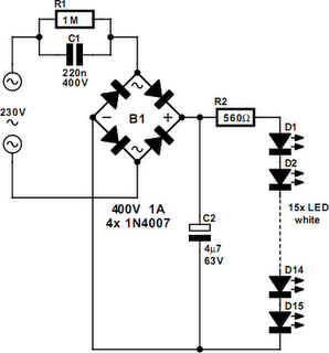
The described LED lamp circuit utilizes a straightforward design that efficiently converts high-voltage AC mains power into a suitable DC voltage for LED operation. The C1 capacitor plays a critical role in voltage regulation, while the bridge rectifier ensures that the LEDs receive the necessary DC supply. The use of a resistor to stabilize current flow is essential for maintaining consistent brightness and preventing LED damage due to fluctuations in current. The careful selection of components, including the electrolytic capacitor and bridge rectifier, enhances the reliability and longevity of the lamp. Moreover, the option to repurpose LEDs from damaged lamps presents an economical alternative for those seeking to create custom lighting solutions. Overall, this circuit exemplifies a practical application of LEDs in home lighting, demonstrating both efficiency and innovation in electrical design.Did it ever occur to you that an array of white LEDs can be used as a small lamp for the living room If not, read on. LED lamps are available ready-made, look exactly the same as standard halogen lamps and can be fitted in a standard 230-V light fitting.
We opened one, and as expected, a capacitor has been used to drop the voltage from 230 V to the voltage suitable for the LEDs. This method is cheaper and smaller compared to using a transformer. The lamp uses only 1 watt and therefore also gives off less light than, say, a 20 W halogen lamp. The light is also somewhat bluer. The circuit operates in the following manner: C1 behaves as a voltage dropping resistor` and ensures that the current is not too high (about 12 mA). The bridge rectifier turns the AC voltage into a DC voltage. LEDs can only operate from a DC voltage. They will even fail when the negative voltage is greater then 5 V. The electrolytic capacitor has a double function: it ensures that there is sufficient voltage to light the LEDs when the mains voltage is less than the forward voltage of the LEDs and it takes care of the inrush current peak that occurs when the mains is switched on.
This current pulse could otherwise damage the LEDs. Then there is the 560-ohm resistor, it ensures that the current through the LED is more constant and therefore the light output is more uniform. There is a voltage drop of 6. 7 V across the 560- resistor, that is, 12 mA flows through the LEDs. This is a safe value. The total voltage drop across the LEDs is therefore 15 LEDs times 3 V or about 45 V. The voltage across the electrolytic capacitor is a little more than 52V. To understand how C1 functions, we can calculate the impedance (that is, resistance to AC voltage) as follows: 1/(2 ·f ·C), or: 1/ (2 ·3.
14 ·50 ·220 ·10-9)= 14k4. When we multiply this with 12 mA, we get a voltage drop across the capacitor of 173 V. This works quite well, since the 173-V capacitor voltage plus the 52-V LED voltage equals 225 V. Close enough to the mains voltage, which is officially 230 V. Moreover, the latter calculation is not very accurate because the mains voltage is in practice not quite sinusoidal. Furthermore, the mains voltage from which 50-V DC has been removed is far from sinusoidal. Finally, if you need lots of white LEDs then it is worth considering buying one of these lamps and smashing the bulb with a hammer (with a cloth or bag around the bulb to prevent flying glass!) and salvaging the LEDs from it.
This can be much cheaper than buying individual LEDs 🔗 External reference
Related Circuits

What is the recommended frequency for the Low Pass Filter used to control the contrast of an LCD? I want to adjust the contrast of an LCD using PWM. To effectively control the contrast of an LCD using Pulse Width...

The Keypad Controlled Switch No2 Circuit operates with a 12-volt supply but is compatible with voltages ranging from 5 to 15 volts. The only requirement is to select a relay that matches the desired supply voltage. The Keypad Controlled Switch...

How many different conditions can be indicated with just one LED? Two, perhaps three? Using this simple circuit, many more can be signaled! This circuit employs a two-color LED, which consists of two light-emitting chips, typically red and green,...

An electret microphone feeds a bandpass filter circuit (IC1A), which subsequently drives a comparator. This comparator activates Q1, a switch that conducts when audio signals from IC1B cause D1, C4, R6, and R7 to bias it ON. The circuit begins...
This LED flasher circuit utilizes a 555 integrated circuit (IC) and is designed to drive multiple LEDs. Notably, connecting several LEDs in series does not increase the power consumption. The LED flasher circuit based on the 555 timer IC is...

The TMS320F2812 Evaluation Board is specifically designed for developers in the digital signal processing (DSP) field, as well as for beginners. The F2812 kit is structured to allow easy access to all the features of the DSP. The TMS320F2812...
Warning: include(partials/cookie-banner.php): Failed to open stream: Permission denied in /var/www/html/nextgr/view-circuit.php on line 713
Warning: include(): Failed opening 'partials/cookie-banner.php' for inclusion (include_path='.:/usr/share/php') in /var/www/html/nextgr/view-circuit.php on line 713