
Multi-Colour LED

The circuit utilizes a two-color LED to signal multiple conditions through a simple yet effective design. The LED, comprising red and green diodes, allows for independent activation, enabling the generation of various colors based on the current supplied to each diode. This flexibility permits the observation of distinct colors, including orange and yellow, achieved by manipulating the current ratios.
The CMOS 4503 three-state buffers serve as the driving mechanism for the LED, providing sufficient output current to illuminate the diodes effectively. Current limiting is accomplished through resistors R1 to R6, offering a practical means to customize brightness and color intensity. This feature encourages experimentation, allowing users to tailor the visual output to specific preferences.
The circuit's logic is designed to interpret three input states, ensuring that only one input can be active at any time, while the fourth state is represented by all inputs being low. The NAND gate, IC1, plays a crucial role in decoding these states, facilitating the correct LED illumination based on input conditions.
An oscillator circuit composed of gates IC1a and IC1b introduces a dynamic flickering effect, enhancing the visual feedback provided by the LED. This oscillator operates at a frequency of approximately two pulses per second, controlled by the inputs d' and e'. The design incorporates a power-saving mode, allowing the circuit to enter a standby state when specific conditions are met, thereby reducing power consumption during inactivity.
The circuit is versatile in terms of supply voltage, functioning effectively within a range of 5 V to 16 V, which broadens its application potential. Proper handling of unused inputs is essential to prevent erratic behavior, and connecting them to ground via appropriate resistors ensures stable operation. Overall, this circuit exemplifies an innovative approach to signaling multiple conditions using a single LED, leveraging the capabilities of modern CMOS technology.How many different conditions do you reckon may be signalled with just one LED Two, maybe three Using this simple circuit, a lot more! Admittedly, a two-colour LED is used here. Such a device consists of two light-emitting chips, usually red and green, encapsulated in the same case.
It has three pins: two for the anodes, and one for the common c athode. In this way, each diode can be activated separately. Various mixed colours may be obtained by varying the current through the two diodes. At least four discrete colours are then easily perceived: pure red, pure green, orange (IR ‰ 2IG) and yellow (IG ‰ 2IR). In the present circuit, the LED elements are driven by CMOS three-state buffers type 4503, which, unlike most CMOS ICs from the 4000 series, are capable of supplying up to 10 mA of output current.
The LED currents are limited by resistors R1 through R6, whose values invite experiments with brightness and colours according to your own taste. The circuit was originally developed to indicate the state of three inputs, a, b, and c (non-binary, i.
e. , only one of these is at 1 at any time), with the configuration (a=b=c=0) representing the fourth state. The latter is decoded by NAND gate IC1. An additional effect is produced by gates IC1a and IC1b, which are connected up into an oscillator circuit producing approximately two pulses per second.
These pulses are used to control the common-enable input, DA (pin 1) of the 4503, so as to produce a flickering effect. The oscillator is controlled by means of inputs d` and e`. Pulling both of these logic high disables the oscillator and the LED driver. With e=0 and d=1 the outputs of the 4503 are switched to three-state, and the circuit is in power-down standby mode.
Although designed for a 12-V supply voltage, the circuit will happily work at any supply voltage between 5 V and 16 V. Non-used inputs of CMOS ICs must, of course, be tied to ground via 10-100 kW resistors. 🔗 External reference
Related Circuits

Build a 10W LED flashlight that features swappable UV, IR, and visible light heads. This flashlight is designed to complement a photographer's toolkit for applications such as light painting, infrared illumination, UV-reflected photography, or UV fluorescence photography. The flashlight...

After constructing a Pulse Width Modulator for high-power LEDs, another LED modulator was developed for an optical transceiver. This project utilized a different approach, focusing solely on linear techniques for audio modulation. Similar to the PWM circuit, this circuit...
All LEDs require some form of current limiting. Connecting an LED directly to the power supply will burn it out almost instantly. Overdriving, even briefly, will significantly reduce its lifespan and light output. Fortunately, driving a single or a...
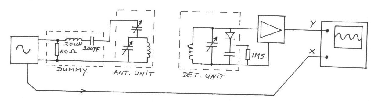
The frequency remains constant, oscillating between two predetermined values. On the oscilloscope display, a frequency spectrum is observed, showcasing the response curves of the two circuits. The input voltage of the receiver is 0.1 Volt peak-to-peak, while the voltage...

This circuit is for a temperature controlled constant current battery charger. It works with NICD, NIMH, and other rechargeable cells. The circuit works on the principle that most rechargeable batteries show an increase in temperature when the cells become...
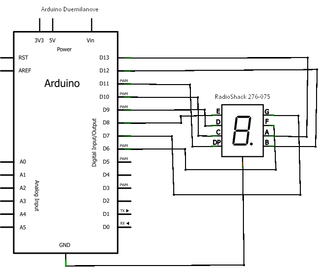
If you're not familiar with the Arduino, it is an open-source electronics prototyping platform based on flexible, easy-to-use hardware and software. It has a small microcontroller, a USB port to connect to your computer for programming, a power socket...
Warning: include(partials/cookie-banner.php): Failed to open stream: Permission denied in /var/www/html/nextgr/view-circuit.php on line 713
Warning: include(): Failed opening 'partials/cookie-banner.php' for inclusion (include_path='.:/usr/share/php') in /var/www/html/nextgr/view-circuit.php on line 713