
Mains Pulser Circuit
The pulser circuit operates by utilizing a timer IC configured in a monostable or astable mode, depending on the desired application. The timer's timing intervals are set by selecting capacitors of different values, which can be easily modified through jumper settings. This flexibility allows users to tailor the timing characteristics to specific needs, whether for testing equipment or machinery operation.
The power supply section, consisting of transformer Tr1, the bridge rectifier, and regulator IC1, ensures that a stable 12V output is maintained, which is critical for the reliable operation of the timer and relay. The relay, controlled by the timer IC, features double-pole contacts that can handle the switching of mains voltage, ensuring that both the live and neutral lines are appropriately managed for safety.
The inclusion of indicator LEDs provides visual feedback on the operation of the circuit, enhancing usability by allowing operators to quickly ascertain the status of the mains supply. The protective fuses are vital components that prevent damage to the circuit and connected devices from potential overloads or short circuits, ensuring robust and safe operation over time.
Overall, this pulser circuit is a versatile tool for various applications requiring timed control of mains voltage, combining safety features with user-friendly adjustments to meet different operational requirements.The pulser is intended to switch the mains voltage on and off at intervals between just under a second and up to 10 minutes. This is useful, for instance, when a mains-operated equipment is to be tested for long periods, or for periodic switching of machinery.
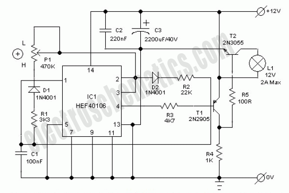
Transformer Tr1, the bridge rectifier, and regulator IC1 provide a stable 12V supply ra il for IC2 and the relay. The timer is arranged so that the period-determining capacitor can be charged and discharged independently. Four time ranges can be selected by selecting capacitors with the aid of jumpers. Short-circuiting positions 1 and 2 gives the longest time, and short-circuiting none the shortest. In the latter case, the 10 µF capacitor at pins 2 and 6 of the timer IC determines the time with the relevant resistors.
The value of this capacitor may be chosen slightly lower. The two preset potentiometers enable the on and off periods to be set. The 1k resistor in series with one of the presets determines the minimum discharge time. The timer IC switches a relay whose double-pole contacts switch the mains voltage. The LEDs indicate whether the mains voltage is switched through (red) or not (green). The 100mA slow fuse protects the mains transformer and low-voltage circuit. The 4 A medium slow fuse protects the relay against overload. 🔗 External reference
Related Circuits
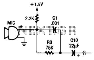
This circuit is suitable for using an electret microphone for various applications. A 1.5-V battery is utilized. CI and R3 provide treble boost and bass cut; they can be eliminated if desired. The described circuit employs an electret microphone, which...

A circuit diagram of a phase-locked loop utilizes an AM686 latched comparator as a voltage-controlled oscillator, along with a TTL latch connected to generate edge-triggered comparators. The VCO and its comparison with the low-pass filter consisting of R1, R2,...
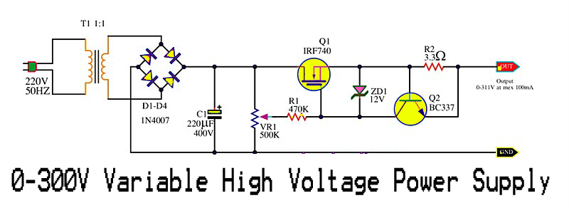
This is a variable high voltage DC power supply circuit that allows for customization of the output voltage ranging from 0 to 311V DC. It includes a current limit protection feature set at approximately 100 mA. The power MOSFET...
This electronic lighting dimmer circuit is designed to control the brightness of incandescent lamps, but it is not suitable for fluorescent lamps. It operates with both 110V and 220V AC power sources. The circuit is connected in series with...

This circuit utilizes a single potentiometer to control a frequency range from 300 Hz to 3000 Hz. A FET operational amplifier is employed at stages A1 and A2. The upper frequency limit is dictated by the gain-bandwidth product of...
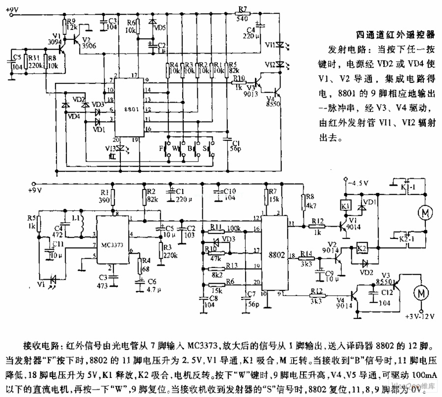
The receiving circuit involves an infrared signal being input to the MC3373 from pin 7 via a phototube. The amplified signal is output from pin 1 and sent to pin 12 of the decoder 8802. When the transmitter F...