
Mains Remote-Alert Circuit Using BC547 Transistor
The Mains Remote-Alert Circuit is designed to provide a notification system that alerts users about the status of mains power. The circuit typically consists of a transmitter and a receiver unit. The transmitter is connected to the mains supply and detects when the power is on or off. This is often achieved using a simple switch or relay that activates when mains voltage is present.
The transmitted signal is usually a low-frequency radio frequency (RF) signal, which is sent wirelessly to the receiver unit. The receiver is equipped with a demodulator that converts the RF signal back into a usable form, triggering an alert mechanism, such as an LED indicator, buzzer, or other notification systems.
Key components of the circuit may include a microcontroller or timer IC that manages the timing of the signal transmission, ensuring that alerts are sent only when necessary. Additionally, the circuit may incorporate filtering capacitors to stabilize voltage levels and prevent false triggering due to noise.
The overall design emphasizes simplicity, making it accessible for hobbyists and engineers alike. The circuit can be easily modified to include additional features, such as adjustable sensitivity or multiple alert types, enhancing its functionality and user experience.
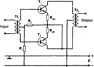
This system is particularly useful in applications where monitoring mains power is critical, such as in remote locations or for individuals who may not be able to physically check power status regularly.The following circuit shows about Mains Remote-Alert Circuit Diagram. Features: simple circuitry, the transmitted signal is conveyed into the . 🔗 External reference
Related Circuits

Circuit diagram schematics of electronic keys, electronic locks, digital electronic locks, transistor code locks, and combination electronic locks. The circuit schematics for electronic locking mechanisms encompass a variety of designs tailored to enhance security and convenience in access control systems....
The schematic shown below is a 555 timer circuit. The NE555 is a well-known integrated circuit that comes in an 8-pin dual in-line package (DIP). There is a vast array of circuits utilizing the 555 IC, which contributes to...
An amplifier is a device that accepts a varying input signal and produces an output signal that varies in the same way as the input but has a larger amplitude. The input signal may be a current, voltage, mechanical...

This timer circuit utilizes a 555 IC timer in conjunction with three 74LS193 counters to control an LED display. The circuit is activated by one individual who turns on the piezo buzzer BZ1 through Q1, simultaneously starting the timer....
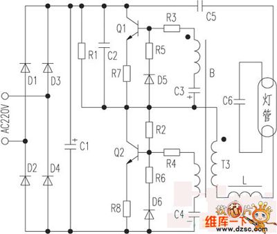
The saving lamp circuit features two main types: glass cover and exposed. The glass cover variants include three series: spherical, cylindrical, and processing types. The first two series consist of four variations: transparent, carved, engraved, and white. These lamps...
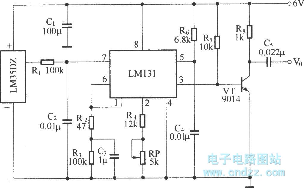
The circuit depicted in the figure integrates a temperature detection system, a temperature-voltage switch, and a voltage-frequency switch to enable remote temperature monitoring. This circuit is connected to a wireless transmission circuit, creating a remote control temperature detection system....
Warning: include(partials/cookie-banner.php): Failed to open stream: Permission denied in /var/www/html/nextgr/view-circuit.php on line 713
Warning: include(): Failed opening 'partials/cookie-banner.php' for inclusion (include_path='.:/usr/share/php') in /var/www/html/nextgr/view-circuit.php on line 713