
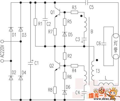
The electronic energy saving lamp maintenance circuit diagram
The saving lamp circuit is designed to accommodate various applications, utilizing both glass cover and exposed types to suit different environments and aesthetic preferences. The glass cover variants not only enhance visual appeal but also provide durability and protection for the internal components. The spherical and cylindrical designs offer versatility in mounting options, while the processing types can be tailored for specific applications, such as decorative lighting or task illumination.
The exposed types, including H, UH-based, 3U, 4U-based, 2D, and screw types, provide additional flexibility in installation. These types are commonly used in settings where direct exposure to the environment is acceptable or desired, such as in outdoor lighting or industrial applications. The categorization by light color allows for targeted lighting solutions, catering to various moods and functionalities. For instance, warm light (2700K) is often preferred in residential settings for its cozy ambiance, while cool light (6400K) is beneficial in workspaces for enhancing visibility and focus.
Furthermore, the incorporation of color temperature options, including the non-irritating 5000K light, emphasizes the importance of user comfort and well-being. This feature is particularly advantageous in environments where prolonged exposure to artificial lighting occurs, such as offices or educational institutions. By closely mimicking natural light, these lamps aim to reduce eye strain and improve overall productivity.
In summary, the saving lamp circuit is a versatile and aesthetically pleasing lighting solution, offering a wide range of configurations and light color options to meet diverse needs in both residential and commercial applications.The saving lamp circuit has the glass cover type and exposed type. Glass cover types have three series of spherical, cylindrical ball, processing type, etc. , the first two series have completely four types of transparent, carving, engraving and white color. It has the advantages of beautiful appearance, easy installation, anti-collision, etc. ; ex posed type has the types of H, UH-based, 3U, 4U-based, 2D and screw type. They also can be divided by the color of light, which can be divided into red, green, blue, yellow (color temperature is 2700K, and it belons to warm light which is similar to incandescent light color), white (color temperature is 6400K, is a cool light which similar to fluorescent light color); the lamps with color temperature in 5000K has no irritation to the eyes as the light color close to natural light. 🔗 External reference
Related Circuits
This is a subwoofer low-pass filter circuit, which is another variant based on the discharge from ST Microelectronics' TL062. The TL062 is a dual high-input impedance J-FET operational amplifier characterized by low power consumption and a high slew rate....
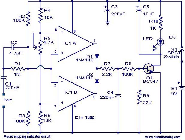
This circuit is designed to detect clipping in a specific waveform. Clipping occurs when the amplitude of a waveform decreases before reaching its expected limit. The circuit activates an LED as an indication that the tested signal is experiencing...
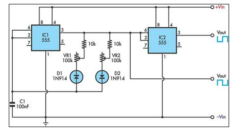
This circuit allows for the independent variation of the on/off times of a 555 timer across a wide range. This capability is not achievable with a conventional 555 timer circuit. The described circuit enhances the functionality of the standard 555...
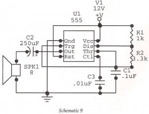
This circuit features an astable oscillator constructed around a 555 timer, generating an alarm tone of 1.8 kHz, which directly drives a speaker. It serves as a fundamental alarm circuit that can be utilized in various projects. Although the...

This simple mock flasher LED simulates the indicator of a sophisticated alarm system. It can be placed in doors, gates, and vehicles to confuse intruders. The mock flasher LED circuit is designed to mimic the flashing behavior of a typical...
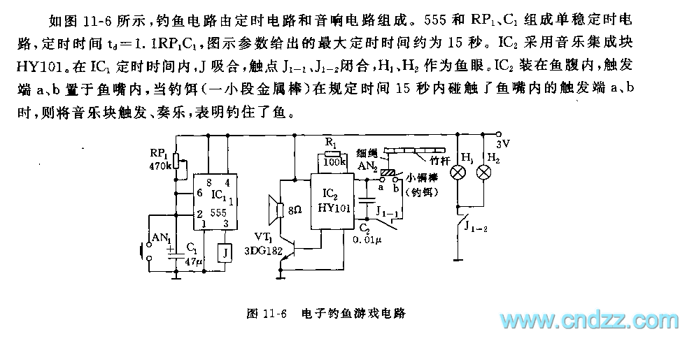
The fishing circuit, as illustrated in figure 11-6, comprises a timing circuit and an audio circuit. The components 555, RP1, and C1 form the single-shot circuit, with the defined time calculated as td = 1.1RP1C1. The maximum defined time...
Warning: include(partials/cookie-banner.php): Failed to open stream: Permission denied in /var/www/html/nextgr/view-circuit.php on line 713
Warning: include(): Failed opening 'partials/cookie-banner.php' for inclusion (include_path='.:/usr/share/php') in /var/www/html/nextgr/view-circuit.php on line 713