
Electronic Keys and Locks Circuits-Digital Code Locks-Combination and Transistor Code Locks
The circuit schematics for electronic locking mechanisms encompass a variety of designs tailored to enhance security and convenience in access control systems.
1. **Electronic Keys and Locks**: These systems typically utilize a microcontroller to manage access permissions. An electronic key, often in the form of a key fob or card, communicates with the lock via RFID or infrared signals. The circuit includes a reader module that detects the key's signal, a microcontroller that processes the input, and a motor driver that actuates the locking mechanism.
2. **Digital Electronic Locks**: These locks employ a keypad interface where users input a numerical code to gain access. The schematic includes a keypad matrix, a microcontroller for code validation, and an actuator for the locking mechanism. Additional features may include an LCD display to provide user feedback and a buzzer for alert signals.
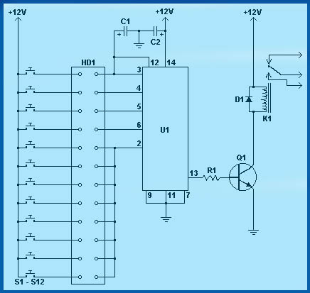
3. **Transistor Code Locks**: This type of lock uses transistors to control the locking mechanism based on a specific input code. The circuit design includes a series of switches or buttons connected to a transistor array, which activates the lock when the correct sequence is entered. The transistors serve as electronic switches, providing a robust method to control the power to the locking mechanism.
4. **Combination Electronic Locks**: These locks require a combination of inputs, often from both a keypad and a biometric sensor. The schematic integrates a microcontroller that processes multiple input types, ensuring enhanced security. The circuit may also feature a backup battery system to maintain functionality during power outages.
Overall, these electronic locking systems represent a convergence of various technologies, including microcontrollers, sensors, and actuators, to provide secure and efficient access control solutions. Each design can be customized based on specific security requirements and user preferences, making them versatile for residential and commercial applications.Circuit diagram schematics of Electronic Keys, Electronic Locks,Digital Electronic Locks,Transistor Code Locks,Combination Electronic Locks.. 🔗 External reference
Related Circuits
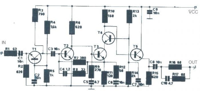
The T1 transistor must be of the BF200 type (or a similar variant), while the other transistors can be of the BF214 type. To achieve high efficiency, the antenna amplifier should be positioned at a short distance from the...
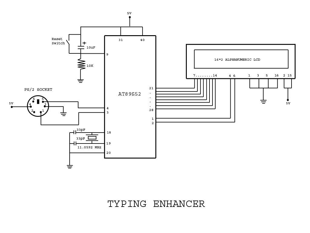
Project with Circuit and Code for a Typing Assistant using the 8051 microcontroller (AT89S52) and the PS/2 keyboard port of a computer. The project also explains the interfacing of the PS/2 port of a computer with the 8051 microcontroller. The...
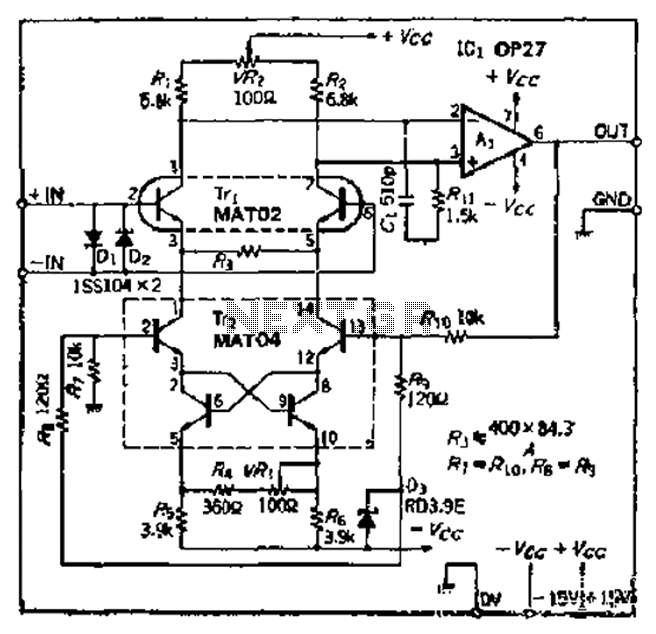
The Bong ordinary differential amplifier circuit differs from a standard differential circuit by incorporating a voltage-current conversion circuit, which consists of resistors R and Rl. The operational amplifier (OP amp) includes a voltage divider that subsequently converts the voltage...
This is a silicon transistor circuit showing typical voltage values. When the forward base/emitter voltage is 0.6 to 0.7 V, the transistor is silicon. Germanium transistors will have a forward base/emitter bias voltage of 0.2 to 0.3 V. This...
To simplify the driver circuit, a multiplexer circuit can be utilized as a solution. With this multiplexed BCD decoder, only one BCD is required. A multiplexer (MUX) is an essential component in digital circuits, allowing multiple input signals to be...
A 30W Class AB power amplifier circuit diagram utilizes a power transistor. To set up the amplifier, adjust the variable resistor R1 to its maximum value and R12 to zero. After completing this setup, activate the amplifier. Adjust R1...
Warning: include(partials/cookie-banner.php): Failed to open stream: Permission denied in /var/www/html/nextgr/view-circuit.php on line 713
Warning: include(): Failed opening 'partials/cookie-banner.php' for inclusion (include_path='.:/usr/share/php') in /var/www/html/nextgr/view-circuit.php on line 713