
mains remote switch
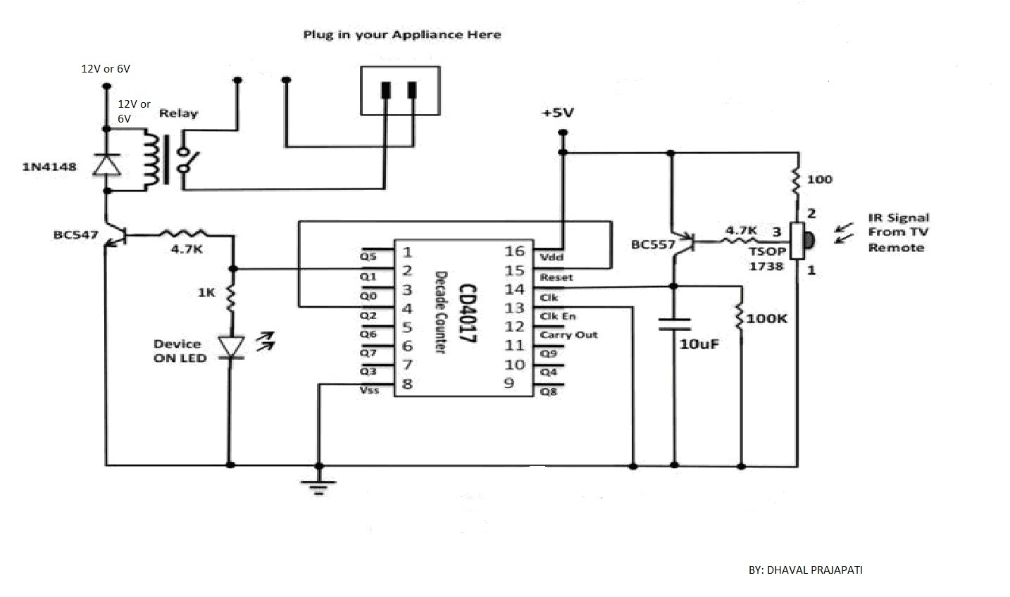
This remotely operated switch circuit utilizes mains voltage to receive control signals, effectively allowing for remote activation of connected devices. The circuit features a relay that connects mains voltage from terminal K1 to K2 upon receiving a signal from a transmitter. The receiver section, comprised of transistor Tr1 and the tuned circuit formed by inductor L1 and capacitor C4, is designed to operate at a frequency of 143 kHz. The sensitivity of the receiver is enhanced by the coupling network C1, Tr1, and C2, which are tuned to the transmitter's frequency.
The relay operation is facilitated by transistor T1, which amplifies the incoming signal. Capacitor C6 smooths the amplified signal, providing the necessary voltage to activate transistor T2, thus energizing the relay. The voltage divider consisting of potentiometer P1, resistor R1, and resistor R2 ensures that T1 is biased correctly, allowing the relay to remain energized even in the absence of a signal.
Diode D1 plays a crucial role in preventing capacitor C5 from charging excessively, which would lead to unwanted conduction in T1. The circuit's design considers the relay's hysteresis, ensuring that the relay disengages when the signal diminishes. It is important to note that the circuit's sensitivity may be influenced by various household factors, and adjustments can be made by modifying the transmitter frequency to a range between 95 kHz and 125 kHz, necessitating corresponding changes to capacitors C1, C2, and C4.
Power for the entire circuit is derived from the mains voltage via a capacitive voltage divider, with resistor R5 limiting the current through the diodes D4 and D7, which are responsible for rectification. Capacitor C7 filters the rectified voltage, while capacitor C8 provides sufficient current for circuit operation. Zener diode D3 regulates the no-load voltage, ensuring safety by preventing dangerous voltages on the input terminals after disconnection from the mains. Test connections A and B allow for additional functionality beyond the relay, provided that users are aware of the circuit's connection to the mains. The relay used in this design must operate at 24 V with a maximum current of 28 mA, ensuring compatibility with the circuit's specifications.This compact design forms a remotely operated switch that receives its control signal via the mains voltage. The switch is operated using the mains remote transmitter` described elsewhere in this issue. With this transmitter, a switch should be connected between pins 1 and 2 of K1. Depending on the application, this must be either a press contact or a make contact. The idea of the mains remote switch` is that a relay is energized in order to connect the mains voltage on K1 through to K2. The receiver` (a somewhat exaggerated term for such a simple design) is formed by Tr1 and the tuned circuit L1/C4.
The network C1/Tr1/C2 serves as a coupled circuit tuned to the frequency of 143 kHz generated by the transmitter. The selectivity is determined by L1/C4 and is primarily dependent on the standard suppression coil L1.
Gain for operating the relay is provided by T1. The amplified signal is smoothed by C6 and provides the voltage necessary to cause T2 to conduct and energize the relay. The voltage divider formed by P1, R1 and R2 provides a bias voltage for T1 in order to increase the sensitivity of the receiver.
This also allows the relay to be energized without a received signal. D1ensures that C5 does not become charged and prevents T1 from conducting even more. The operation of the circuit is based on the fact that the incoming signal is sufficiently strong to overcome the hysteresis of the relay. Once the signal is no longer present, the relay must naturally again release. To be honest, it must be noted that the simple design of this circuit has the disadvantage that its sensitivity may be somewhat inadequate, depending on household circumstances.
One possible solution is to reduce the frequency of the transmitter to the region between 95 and 125 kHz. The values of C1, C2 and C4 will then have to be modified to match, so this is something for readers who like to experiment.
Do not forget that just as with the transmitter, the entire circuit (once it has been switched on, of course) is connected to the mains potential. Power for the transistor stage and the relay is taken directly from the mains voltage using a capacitive voltage divider; R5 is only necessary to limit the current through the diodes to a safe value on switch-on.
Rectification is provided by diodes D4 D7 and ¬ltering by C7. The impedance of C8 is low enough to provide sufficient current. The no-load voltage (when T2 is not conducting and the relay is not activated) is limited by zener diode D3. R6 and R7 discharge C8 immediately after the circuit is disconnected from the mains, in order to prevent any dangerous voltage from remaining on the input terminals.
Connections A and B are provided for test purposes and also allow something other than the relay to be energised (but keep in mind that the circuit is electrically connected to the mains network!). The pinout of the relay is standard, so a type other than that shown in the components list can also be used, as long as you make sure that the operating voltage is 24 V and the operating current does not exceed 28mA.
🔗 External reference
Related Circuits
The SFH505A, manufactured by Siemens, integrates an infrared diode receiver, amplifier, demodulator, and a band-pass filter to minimize interferences. This circuit operates effectively in various applications. The SFH505A is a versatile optical receiver module designed for infrared communication systems. It...
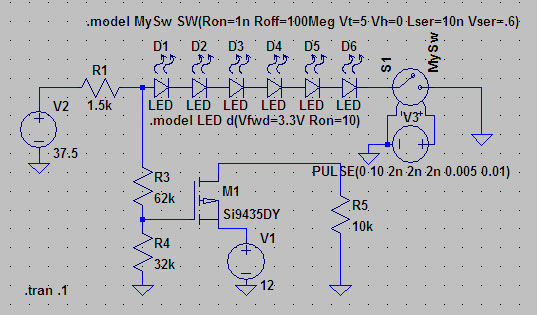
A suitable method to sense when some LEDs in a garage door opener are illuminated. A power source, potentially the same as Vout, connects to a 1.5 kΩ resistor, which then connects to six LEDs followed by a transistor....
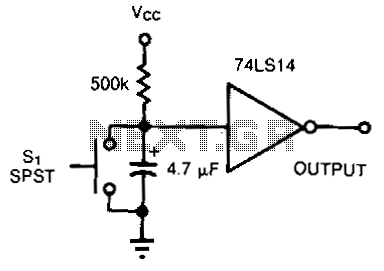
The TTL inverter 74LS14 features an internal 16-kohm pull-up resistor that ensures the gate input is pulled high when the switch is open. Upon closing the switch, a 4.7uF capacitor discharges at the initial contact. If the switch contacts...
The Thermistor, or NTC (Negative Temperature Coefficient) of 10K, is a standard type. Most types will work. The one in the diagram is a 10K model made by Fenwal (#197-103LAG-A01). The resistance lowers as the surrounding temperature increases, which...
The circuit utilizes a 4-bit encoder to generate data, which is then modulated using an RF modulator for transmission. On the receiving end, the signal is demodulated, and a decoder retrieves the 4-bit data. The pin configuration for the...
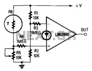
The output becomes high when a predetermined temperature is surpassed. A fixed half-supply reference voltage provides a reference current to the inverting input, while a variable current is supplied to the non-inverting input. Resistor R6 functions as a negative-temperature-coefficient...
Warning: include(partials/cookie-banner.php): Failed to open stream: Permission denied in /var/www/html/nextgr/view-circuit.php on line 713
Warning: include(): Failed opening 'partials/cookie-banner.php' for inclusion (include_path='.:/usr/share/php') in /var/www/html/nextgr/view-circuit.php on line 713