
Over-Temperature Switch
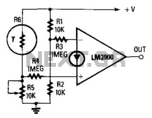
The described circuit utilizes an operational amplifier (op-amp) in a temperature sensing application. The core functionality hinges on the relationship between the temperature and the voltage across the NTC thermistor (R6). As the temperature rises, the resistance of the NTC thermistor decreases, resulting in an increase in the voltage at the junction of R5 and R6. This junction voltage is critical as it is compared against a fixed reference voltage derived from the half-supply voltage.
The op-amp is configured in a comparator mode, where the inverting input receives a constant reference current that establishes a stable reference point. The non-inverting input, connected to the junction of R5 and R6, receives a variable current that changes with temperature variations. When the voltage at the non-inverting input exceeds the reference voltage at the inverting input, the output of the op-amp transitions to a high state.
The trip temperature, which determines when the output will switch high, can be finely tuned by adjusting the value of resistor R5. This design allows for flexibility in setting the desired temperature threshold for activation. The overall circuit can be applied in various temperature monitoring and control systems, where precise temperature detection is crucial. Additionally, the incorporation of an NTC thermistor provides a cost-effective and reliable means of temperature sensing.
In summary, this circuit exemplifies a simple yet effective method of temperature measurement and control using an op-amp and an NTC thermistor, with adjustable parameters for tailored applications. The output goes high when a preset temperature is exceeded. A fixed half-supply reference voltage feeds a reference current to the inverting input, and a variable current is fed to the noninverting input. Resistor R6 is a negative-temperature-coefficient (NTC) thermistor, so the potential at the junction of R5 and R6 rises with temperature. The op amp will switch high when that voltage exceeds the half-supply value. The trip temperature can be preset via R5. 🔗 External reference
Related Circuits

This power supply utilizes an SGS-Thomson UC3842 integrated circuit in an off-line flyback regulator configuration, delivering +5 V at 4 A and ±12 V at 300 mA. This design allows for the use of a compact high-frequency (50 kHz)...
A thermally controlled switch operates based on the surrounding temperature without human intervention, except during the construction of the electronic thermostat. This type of switch has numerous practical applications. For instance, it can activate an additional fan when the...
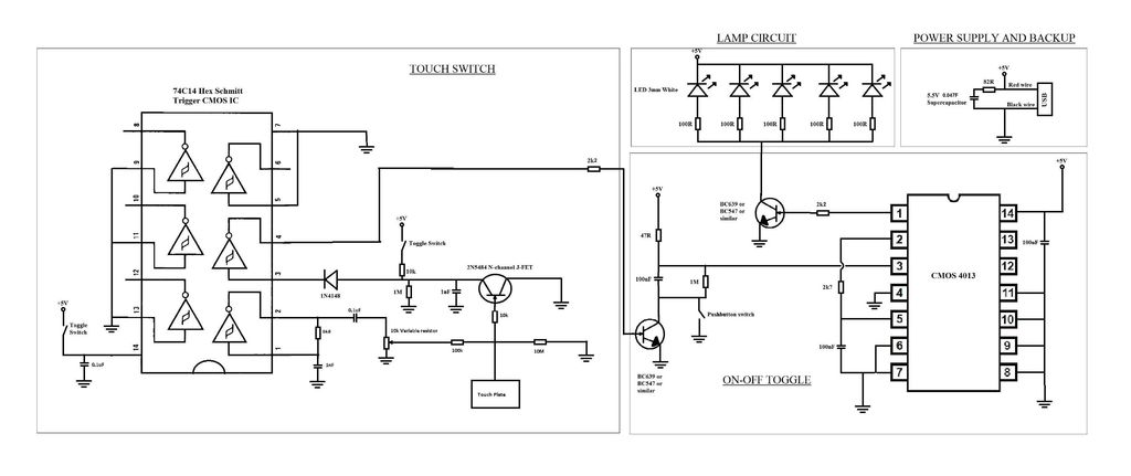
A touch switch for a USB-powered desk lamp is malfunctioning. The circuit diagram, layout, and pictures are provided below. The design incorporates circuits sourced from two websites, specifically the fourth circuit. The output of the touch switch is connected...
This circuit illustrates the TDA1054 tone control stereo preamplifier circuit diagram. Features include the National Semiconductor LM35 integrated circuit, which utilizes semiconductor technology. The TDA1054 is a versatile integrated circuit designed for use in audio applications, particularly in tone control...
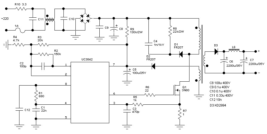
60 Watt Switching Power Supply. Visit the page for an explanation of the related circuit diagram. The 60 Watt Switching Power Supply is designed to convert an input voltage to a regulated output voltage while maintaining high efficiency and compact...
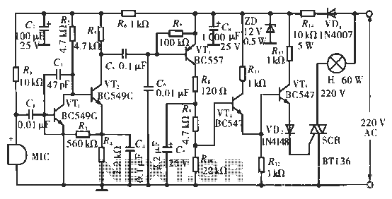
The circuit utilizes condenser microphones to detect sound and convert it into signal variations. This signal is then processed through directly coupled transistors VT1 and VT2, which form an amplification stage before being fed into a switching circuit. The...
Warning: include(partials/cookie-banner.php): Failed to open stream: Permission denied in /var/www/html/nextgr/view-circuit.php on line 713
Warning: include(): Failed opening 'partials/cookie-banner.php' for inclusion (include_path='.:/usr/share/php') in /var/www/html/nextgr/view-circuit.php on line 713