
Mains Trigger Musical Door bell
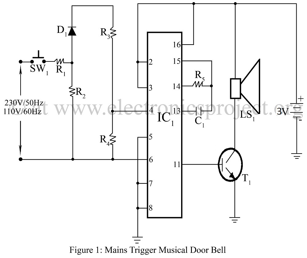
The mains-triggered musical doorbell circuit utilizes the UM3482 integrated circuit, which is specifically designed for generating musical tones. This circuit is activated by a mains voltage signal, enabling it to produce melodies when the doorbell button is pressed. The UM3482 chip includes a built-in tone generator and is capable of playing multiple tunes, making it suitable for various applications in doorbell systems.
The circuit typically consists of the following components: the UM3482 IC, a transformer to step down the mains voltage, a rectifier to convert AC to DC, and additional passive components such as resistors and capacitors to filter and stabilize the power supply. The circuit may also include a push-button switch that, when pressed, triggers the IC to initiate the musical output.
The transformer is crucial as it reduces the high mains voltage to a lower, safer voltage suitable for the circuit. The output from the transformer is then rectified, providing a stable DC voltage to power the UM3482. The musical tones generated by the IC can be amplified using a small speaker or buzzer, allowing for clear sound output.
This design can be further enhanced by incorporating additional features such as adjustable volume control, multiple tune selection via a rotary switch, or even integrating wireless capabilities for remote activation. The versatility of the UM3482 allows for creative modifications, enabling the development of a unique doorbell project tailored to individual preferences.
Overall, this circuit provides an engaging and functional solution for creating a musical doorbell that not only alerts homeowners to visitors but also adds an element of fun and personalization to the traditional doorbell design.Mains Trigger Musical Door bell using musical ic UM3482 circuit diagram with description of mains trigger musical door bell various and unique doorbell project. 🔗 External reference
Related Circuits
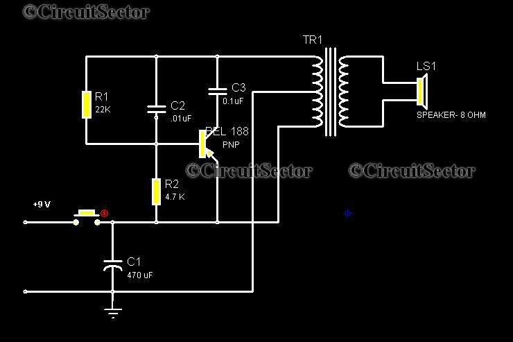
This circuit is a low-cost, one-touch doorbell using a Bel 188 transistor. It is likely one of the most economical bell circuits that can be constructed. The core component of this circuit is the output transformer from a push-pull...

A magnet is positioned on the door, while a magnetic reed switch is installed on the door casing. When the door is closed, the circuit is disabled. When the door is opened, the circuit becomes active. In this circuit design,...
In all the houses exist the bells in the door. All want, they have the possibility of being possible to change the intensity, the tone of sound. With this circuit we have this possibility. With the materials round the...
The circuit is a bell timer. This project utilizes the AT89S52 microcontroller and an I2C EEPROM for storing alarm timings. Additionally, the 7-segment display has been replaced with an LCD display. The DS1307 is employed for real-time clock functionality....

The circuit shown will switch on and off a resistive or inductive load up to 800VA with the possibility to adjust both the on and off period. Switching takes place during the zero crossing of the sine wave. The...
Have you ever accidentally left your front door ajar and had a pet escape? Here is a smart solution to this problem. The circuit is relatively simple but serves as a great example of using a compact circuit to...