
Mains variable Delay circuit
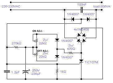
The described circuit employs a silicon-controlled rectifier (SCR) to control the switching of a load, which can be either resistive or inductive, with a maximum rating of 800VA. The operation of the circuit is based on the principle of zero-crossing switching, which minimizes electromagnetic interference (EMI) and reduces stress on the load by ensuring that the switching occurs when the AC voltage is at zero volts.
The adjustable on and off periods provide flexibility in controlling the load, allowing the user to set the on time between 0.3 seconds to 4 seconds and the off time between 0.2 seconds to 10 seconds. This adjustability is typically achieved through the use of timing components such as resistors and capacitors, which define the charging and discharging times in conjunction with the SCR's gate control.
The sensitivity of the SCR's gate is a critical design choice, as it allows for the elimination of large electrolytic capacitors that are often used in similar circuits for timing purposes. This enhances the circuit's reliability and reduces the physical size of the components. However, it is important to note that the frequency of operation may experience slight variations due to environmental factors such as temperature changes, fluctuations in supply voltage, and variations in load conditions. These factors can affect the timing characteristics of the circuit, which should be taken into consideration during design and implementation.
In summary, the circuit is designed for efficient control of AC loads with adjustable timing features, leveraging the characteristics of SCRs to provide a compact and effective solution for switching applications. Proper attention to component selection and circuit layout will ensure optimal performance and reliability in various operating conditions.The circuit shown will switch on and off a resistive or inductive load up to 800VA with the possibility to adjust both the on and off period. Switching takes place during the zero crossing of the sine wave. The switch on point is around the zero crossing but pinpoint accuracy is not guaranteed due to the analogue nature of the circuit.
The on period is adjustable between 0.3 to 4sec while the off period is adjustable between 0.2 and 10sec. The chosen SCR has a sensitive gate: this avoids the use of a large electrolytic capacitor. Frequency of operation is fairly stable although it is slightly affected by temperature, supply voltage and loading conditions. 🔗 External reference
Related Circuits
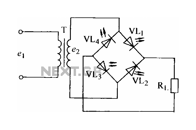
In certain applications, the current from a non-rectified voltage power supply circuit is insufficient. A light-emitting diode (LED) rectifier circuit can be employed to address this issue, serving as a power indicator. It is important to ensure that the...
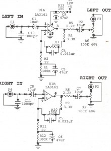
Preamplifiers are utilized to amplify low-level signals, such as those from microphones and tape heads, before they are sent to power amplifiers. Power amplifiers typically exhibit lower sensitivity. The frequency response can also be adjusted and optimized at the...
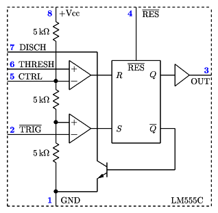
It is a typical Astable Multivibrator (AMV) setup. The capacitor charges through both resistors until it reaches 2/3 of Vcc, which is the level of the internal comparator. This triggers a flip-flop, activating the Discharge output (DIS). The capacitor...
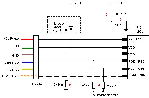
Microchip does not recommend any specific circuit for In-Circuit Serial Programming (ICSP). Various diagrams exist for different tools, such as Pro Mate and PICKit2, which feature similar circuitry with minor variations. Some schematics may suggest resistor values that are...
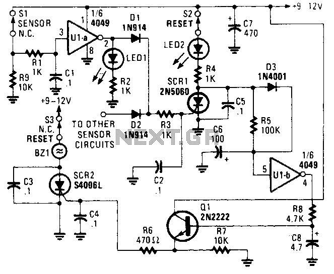
The alarm/sensor circuit is constructed using two SCRs, a transistor, a 4049 hex inverter, and several supporting components, which together create a closed-loop detection circuit featuring a delay mechanism. This delay allows entry into a protected area and deactivation...
The human approach detector circuit consists of an integrated operational amplifier, a gate circuit, and a resistor-capacitor unit as illustrated in the diagram. The 1 MHz oscillator is composed of a reverser T1, a 1 MHz crystal oscillator, and...