
Electronic siren circuit
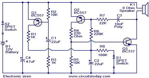
The electronic siren circuit employs a robust design utilizing three transistors to achieve its function. The primary components of this circuit include the transistors Q1, Q2, and Q3, where Q2 and Q3 are configured as a complementary pair. This configuration is essential for generating the astable multivibrator oscillator, which produces a square wave signal to drive the speaker effectively.
In operation, when power is initially applied to the circuit, transistor Q1 activates, charging capacitor C2 to its maximum voltage. This capacitor serves as a critical component in regulating the oscillation frequency. The inclusion of push button switch S1 allows for user interaction, enabling the siren to be activated on demand. Upon pressing S1, capacitor C2 begins to discharge through resistor R8, leading to a gradual increase in the oscillation frequency. Initially, the frequency is low, but as the charge on C2 diminishes, the frequency escalates to a higher range, creating the characteristic sound of the siren.
The design also incorporates resistor R6, which plays a vital role in the recharging phase of capacitor C2 after the push button is released. The base-emitter junction of transistor Q2 provides a pathway for the positive voltage to recharge C2, thereby controlling the oscillation cycle. The gradual decrease in frequency as C2 charges back to the battery voltage ensures a smooth transition in the sound output, enhancing the overall functionality of the siren circuit.
This compact siren circuit is highly versatile, making it suitable for various applications beyond simple alarms, including integration into security systems and industrial alert mechanisms. The design's simplicity and effectiveness make it an ideal choice for projects requiring an audible warning signal.This is a compact electronic siren circuit based on three transistors. This circuit is suitable for in corporating with other alarm or siren projects such as burglar alarms, automatic factory sirens etc or a simple push to on alarm. The electronic siren circuit given here is based on a complementary transistor pair consisting of Q2 & Q3 (BC557 & BC
37) wired as an astable multivibrator oscillator, which directly drives the speaker. The transistor Q1 is used toprovide a full chargeon capacitor C2 when power is turned ON. When push button switch S1 is pressed, the capacitor C2slowly discharges through resistor R8. This makes the circuitto oscillate at a low frequency that increases to a high frequency and kept indefinitely as the capacitor is fully discharged. When the switch P1 is released, the output frequency decreases slowly as C2 is charged to the positive voltage through resistance R6 and the Base-Emitter junction of tramsistor Q2.
When C2 is fully charged to the positivebattery voltagethe circuit stops oscillating. 🔗 External reference
Related Circuits
An FM modulator that modulates a carrier frequency with the composite signal, and an RF amplifier that provides enough power to be transmitted through an antenna. Here is the schematic diagram of the FM transmitter circuit: The core of...
The circuit with the original m rJ bamboo is designed similarly. It includes a secondary disk that functions as a floodlight. A grass-flow filter is incorporated for a light input. An electric connection is established with a door button...
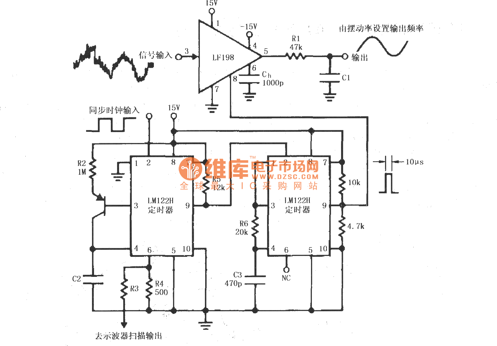
A synchronous clock signal is fed into a cascade of timer circuits composed of two LM122H devices. The synchronization clock is then converted into a pulse of the desired width, which is added to the LF198 logic end (pin...
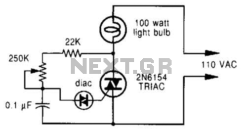
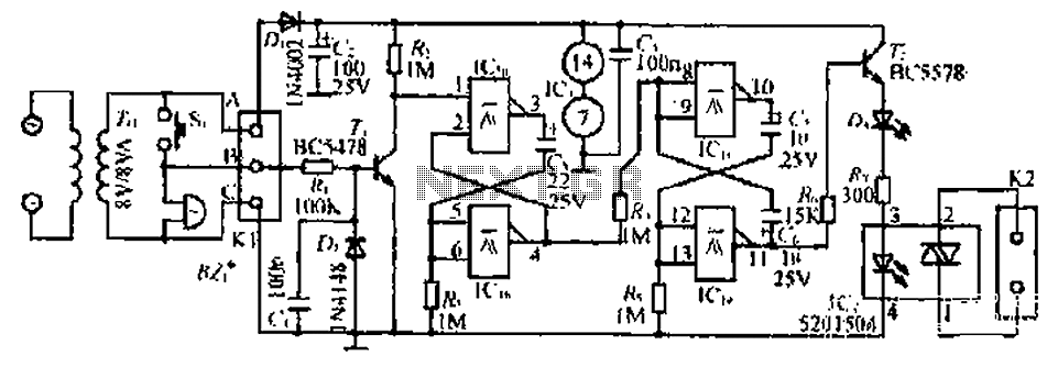
A phase-controlled dimmer delays the triac turn-on to a selected point in each successive AC half cycle. This circuit is suitable only for incandescent lamps, heaters, soldering irons, or universal motors that have brushes. A phase-controlled dimmer is an electronic...
Ambient light is increasingly being utilized as an energy source. To assist designers in developing such systems, this circuit effectively measures ambient light intensity across four decades of measurement. The design is cost-effective, and with the sensor housed in...

The camera has been wired with external shutter leads, and a method is needed to trigger them. These leads must be connected together via a relay at regular intervals, approximately every 2 seconds, starting from launch. A 555 timer...