
make this one transistor radio receiver

The single transistor radio circuit operates on the principle of amplitude modulation (AM) reception, utilizing a minimalistic design that emphasizes efficiency and ease of assembly. The core component, a single transistor, serves dual purposes: it amplifies the weak audio signals received from the antenna and demodulates the amplitude-modulated signals to extract audio information.
The radio circuit typically begins with an LC (inductor-capacitor) tuned circuit, which is responsible for selecting the desired frequency from the radio spectrum. This tuned circuit is designed to resonate at the frequency of the desired radio station, allowing it to filter out other frequencies. The output of the LC circuit is a weak signal that is then coupled to the base of the transistor through a coupling capacitor. This capacitor is critical as it blocks any DC voltage present, allowing only the AC audio signal to pass through to the transistor.
Once the signal reaches the transistor's base, it is amplified. The transistor operates in its active region, where even small changes in base current result in significant changes in collector current, thereby amplifying the audio signal. The amplified output can then be fed to headphones or a speaker, allowing the user to hear the broadcast.
The design also features a unique automatic switch mechanism facilitated by the headphone jack. When headphones are plugged in, the circuit is completed, allowing current to flow and the radio to function. Removing the headphones interrupts the circuit, effectively turning off the radio. This design choice enhances the compactness and user-friendliness of the radio, as it eliminates the need for additional components such as external switches.
Overall, the single transistor radio exemplifies a balance between simplicity and functionality, making it an ideal project for beginners in electronics. Despite its limitations in selectivity and sensitivity, it provides an excellent introduction to radio technology and circuit design principles.This is probably the simplest radio that one could ever imagine of making. The circuit is so simple that it could be finished assembling within a few minutes and you are already listening your favorite programs over it. The circuit of a single transistor radio shown here though looks pretty ordinary, incorporates all the above stages and thus
becomes just suitable for receiving the radio stations. However simplicity will always involve some drawbacks also, here the present design will be capable of receiving only strong stations and also selectivity might not be very pleasing, typically if there are a couple of strong stations mingling around the band. The figure below shows how the single transistor radio can be made, we can clearly see that it just involves a single transistor as the main active component.
The concentrated but very low in power signal from the above LC tuned stage is fed to the base of the transistor which as performs the function of a demodulator as well as a amplifier stage. The coupling capacitor at the base of the transistor makes sure only the radio information passes to the transistor while the DC component from the supply is appropriately blocked.
Plugging in the headphone initiates the circuit and the circuit starts operating with its functions and the switches OFF itself when the headphone is removed from the circuit. This eliminates the need of an external switch to be associated with the circuit, making the unit very compact.
🔗 External reference
Related Circuits
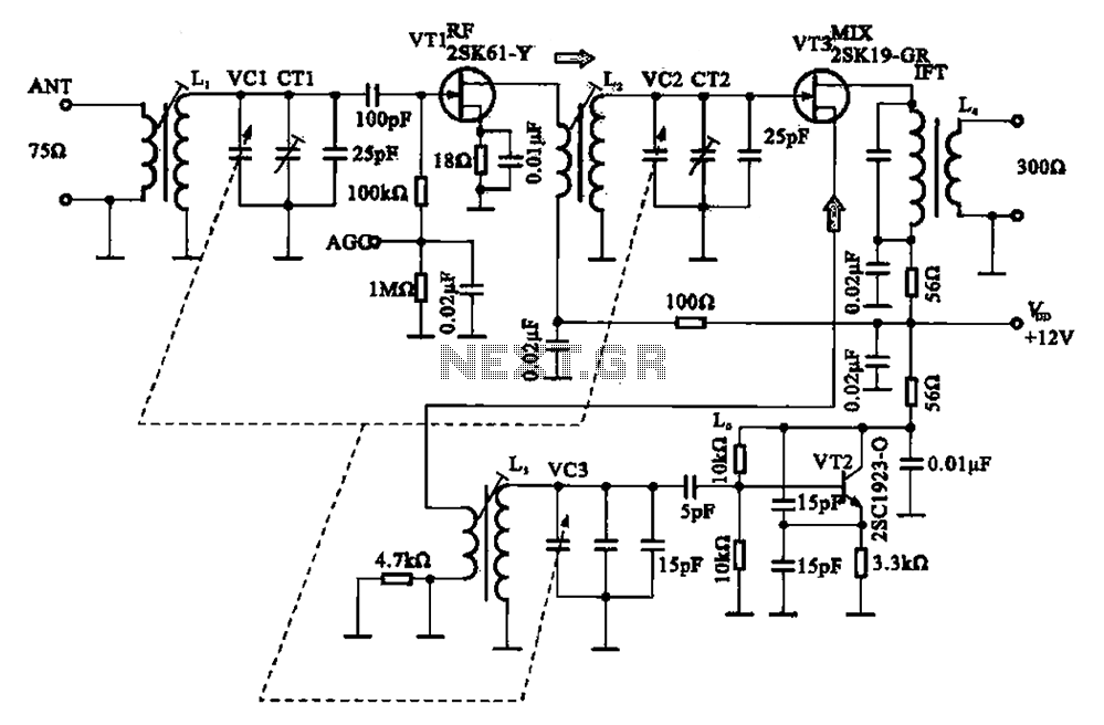
The FM radio circuit consists of a high-frequency amplifier (VT1), a mixer and local oscillator (VT2), and additional components. The circuit includes an FM radio antenna for signal detection, with an input transformer (L1) connected to a gate transistor...
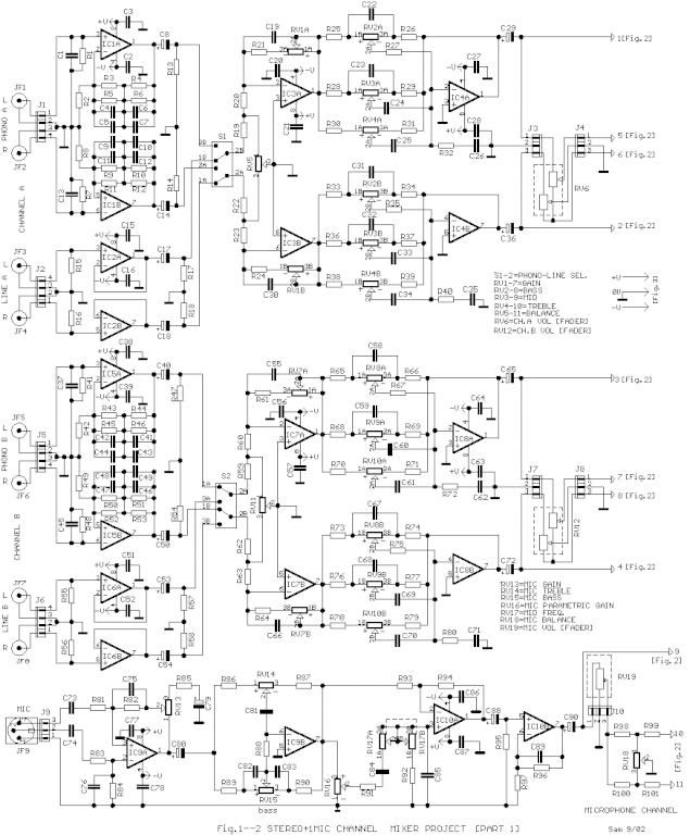
The circuit is designed to provide two channels on a stereo mixer intended for microphones, incorporating a crossfader operation. It utilizes the NE5532 integrated circuit. The stereo mixer circuit features two independent channels, each capable of handling microphone input signals....
The Metal-Oxide-Semiconductor Field-Effect Transistor (MOSFET) is analogous to the Junction Field-Effect Transistor (JFET) in several aspects. Both types are voltage-driven unipolar devices that rely on either electron or hole movement, but not both, unlike bipolar transistors. A key structural...
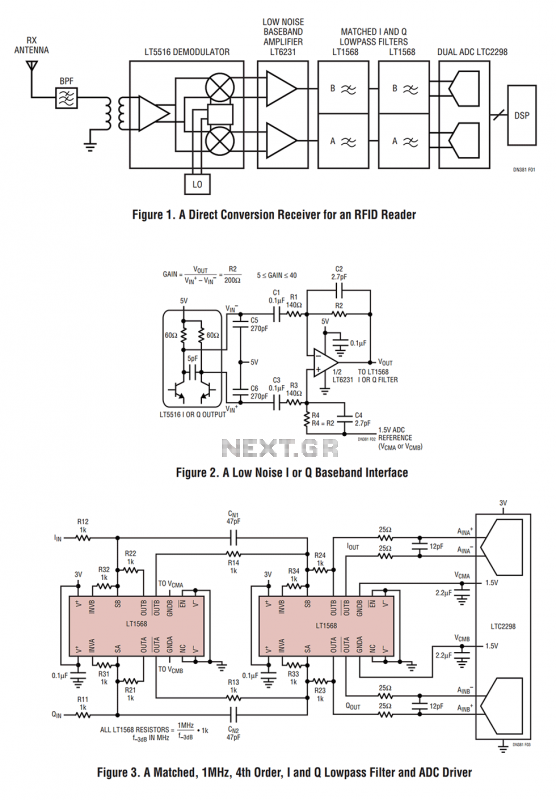
Figure 1 shows the block diagram of a direct conversion RF receiver—the receiver demodulates an RF carrier directly into a baseband signal without an intermediate frequency down-conversion (a zero IF receiver). The antenna, shared by both the transmitter and...
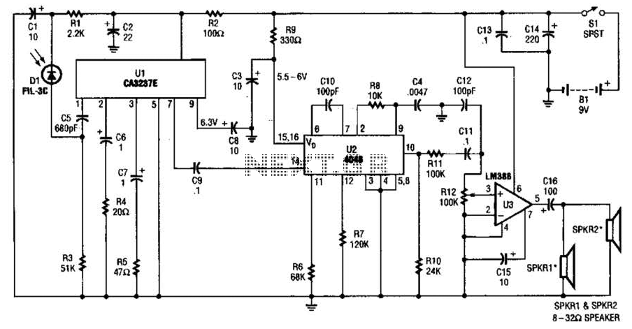
The infrared (IR) detector diode D1 captures the IR signal at approximately 40 kHz and transmits it to U1, a high-gain preamplifier, which then sends the signal to U2, a 4046 phase-locked loop (PLL) configured as a frequency modulation...
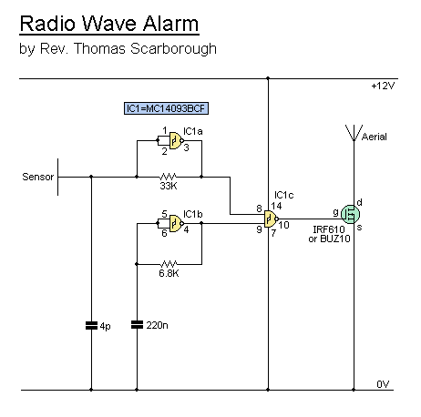
This simple alarm circuit can effectively alert users to the presence of an intruder, providing notification before they even reach the doorstep. The circuit is designed to be straightforward and efficient, utilizing basic electronic components to create an effective security...