
Stereo Mixer for Microphone with 2 Channels

The stereo mixer circuit features two independent channels, each capable of handling microphone input signals. The NE5532 operational amplifier is employed in both channels to ensure high fidelity and low noise performance, which is critical for audio applications. This op-amp is known for its excellent specifications, including low total harmonic distortion and high slew rate, making it suitable for audio processing.
Each channel includes a gain stage to amplify the microphone signal before it is mixed. The crossfader mechanism allows for smooth transitions between the two audio channels, enabling the user to blend the signals seamlessly. This is particularly useful in live sound environments or studio settings, where precise control over audio levels is necessary.
The circuit layout includes input connectors for the microphones, typically XLR or TRS jacks, followed by the gain stage implemented with the NE5532. The output of each channel feeds into the crossfader circuit, which consists of a potentiometer that adjusts the relative levels of the two signals. The output of the crossfader is then sent to a master output stage, which may include additional buffering or amplification to drive the final output to speakers or recording devices.
Power supply considerations for the NE5532 must also be addressed, typically requiring a dual power supply (e.g., ±15V) to ensure optimal performance. Proper decoupling capacitors should be placed close to the power supply pins of the op-amps to minimize noise and maintain stability.
Overall, this circuit design provides a robust solution for mixing microphone signals with the added functionality of a crossfader, making it suitable for various audio applications.The circuit was designed to provide 2 channels on a stereo mixer that will be used for microphones while having a crossfader operation. NE5532 an intern.. 🔗 External reference
Related Circuits
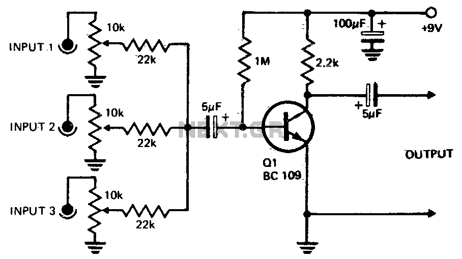
Three or more inputs with individual level controls feed into the base of Q1, which provides a voltage gain of 20. The circuit design involves a transistor amplifier configuration where three or more input signals are managed through individual level...
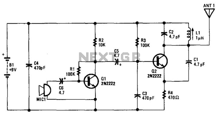
Q1 amplifies the output from an electret microphone (MIC1). The audio signal is fed into oscillator Q2, which modulates the signal. Additionally, L1 and C1 form a tank circuit designed for operation in the 88-MHz frequency range. The antenna...
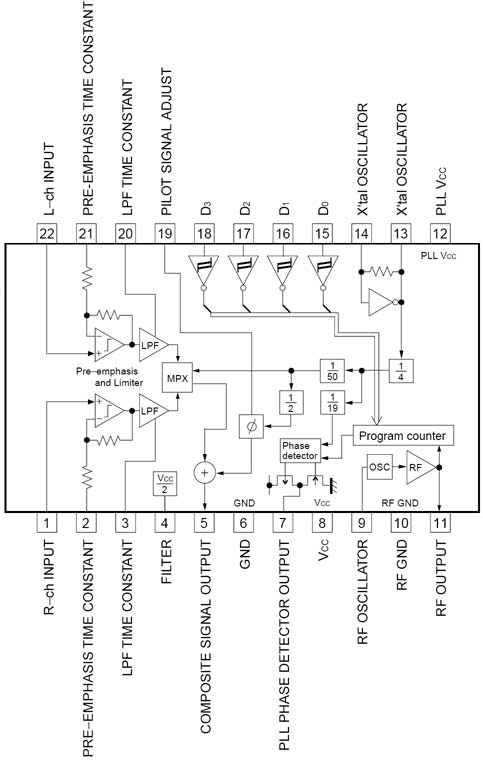
The BH1417 FM Transmitter architecture from RHOM is a compact solution that integrates multiple features into a single package. It includes pre-emphasis and a limiter to ensure that music is transmitted at the desired audio level, as well as...
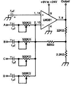
LM381 4-channel audio mixer circuit design project using a few common electronic parts. The LM381 audio mixer circuit is designed to combine audio signals from four separate channels into a single output. This circuit employs the LM381 integrated circuit, which...
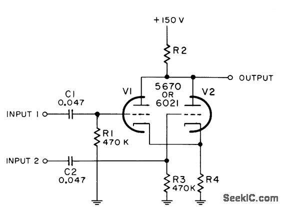
The combination of video signals with pulses involves the inversion of the input signal. The resistor R4 is specified as 270 ohms for the 5670 model and 470 ohms for the 6021 model. Additionally, R2 is set to 680...
This microphone circuit was submitted by Lazar Pancic from Yugoslavia. The sound card for a PC typically features a microphone input, speaker output, and occasionally line inputs and outputs. The microphone input is designed specifically for dynamic microphones with...