
Management of Locomotive Tractive Energy Resources
The TEP-60 diesel engine starter system is designed to operate efficiently in conjunction with current accumulators, allowing for the effective management of battery current both with and without the inclusion of a supercapacitor block. The operational characteristics of the induction traction motor are critical, especially concerning its torque-speed relationship during regenerative braking and traction phases. The AC/AC current system for the electric locomotive incorporates multiple components that facilitate the control and conversion of energy, ensuring optimal performance during various operational modes.
The hybrid traction system configuration, which integrates a diesel engine with synchronous and induction traction motors, showcases a versatile approach to energy management, particularly during regenerative braking. The system's design emphasizes the importance of energy recovery and efficient power distribution, utilizing advanced components like IGBT transistors and analog-to-digital converters to enhance control and responsiveness.
The complementary energy management system is integral to maintaining operational efficiency, particularly in managing energy transitions between traction and braking modes. The incorporation of a supercapacitor block alongside conventional batteries further enhances the system's ability to stabilize catenary current while maximizing energy savings.
Overall, the detailed circuit diagrams and operational parameters presented in this research highlight the complexities of modern traction systems, underscoring the importance of advanced energy management strategies in improving the performance and sustainability of electric and hybrid traction vehicles.The diagrams of starting up of the TEP-60 diesel engines starter in chain of current accumulators: 1- baterry current without SCB, when traction generator operates in a starter mode; 2- baterry current with SCB, when traction generator operates in a starter mode Figure 8. Torque-speed characteristic of induction traction motor`s regenerative braking and traction modes by changing
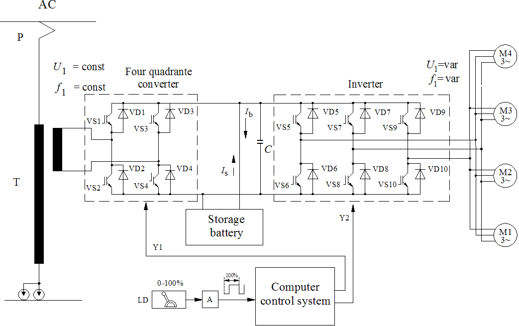
main frequency f1 ’fi ’ parameters: no1 noi is AC traction motor`s no ’load speed Figure 9. A circuit diagram of AC/AC current system electric locomotive regenerative braking energy computer control system: M1-M4 AC traction motors; LD- locomotive driver; A- analogic digital converter; T- traction transformer; P- pantograph; VS1-VS10-IGBT transistors; VD1-VD10-diodes; Y1-four quadrant drive control signals; Y2- inverter drive control signals; Ib-braiking current; Is- stored current; WS1-WS4- wheel-sets Figure 10. A circuit diagram of Hybrid Traction System configuration with AC traction motors: DM-diesel engine; G-synchronous traction generator; M-induction traction motor.
Figure 11. AC/AC power structure diesel-electric locomotive complementary energy management system in regenerative braking and traction mode: DM-diesel engine; G-synchronous traction generator; M- AC traction motor. Mb- electromagnetic moment in the braking mode; n-speed of the rotor; A-energy generation part in the traction mode; B-energy generation part in the braking mode.
Figure 13. Block circuit diagram of the Hybrid Traction System diesel engine start operation mode: DM- diesel engine; CB- conventional battery; K-contactor; Figure 19. Complementary principled scheme of energy saving and catenary current stabilization structure: CB- conventional batteries; SCB-super capacitors block Figure 20.
Scheme of energy management system structure: IR regenerative current; IP ”traction mode current; K- semiconductor key for energy direction control Figure 24. J high-speed disconnector; P phantograph; 4Q1, 4Q2 four-quadrant converters; I1, I2 inverters; M1, M2 AC asynchronous traction motor; C energy accumulation condenser; X1, X2 secondary traction transformer windings current sensors; ST primary winding traction transformer current sensor; A1, A2 secondary traction transformer windings; A3 secondary traction transformer winding for measurement of contact network voltage (25 kV); BU flattening voltage sensor; Rb dynamic braking resistor; VS1 IGBT-transistor braking current (braking force) value regulator; BR1, BR2 speed sensors of traction motors; VD1, VD2 diodes; C capacitor; 1, 2, 3, 4, 5 analogical-digital converters; ”n1, ”n2 asynchronous traction motors speed variation; WS1, WS2 wheelsetsThe scheme of the train EJ-575 traction-electrodynamical braking parameters practical research, using a personal computer Figure 25.
ITr diagram of primary traction transformer winding current variation (A); UTr diagram of contact network voltage variation(V); flattening voltage Ud variation diagram (V); V diagram of speed variation of the train (km/h); t time (s)Parameters values of the double-deck electric train EJ-575 energy-management in traction-electrodynamic braking modes Figure 26. 0 t1 traction cycle 1T; t1 t2 electrodynamic braking cycle 1S; t2 t3 traction cycle 2T; t3 t4 electrodynamic braking cycle Diagrams showing variation of contact network energy P(t) and electrodynamic braking P(t) energy consumed in electric double-deck train EJ-575 The paper addresses some basic theoretical and engineering problems of electrodynamic braking, presenting methods of braking force regulation and using of regenerative braking returning energy (energy saving systems) and diesel engine or any form of hybrid traction vehicles systems, circuit diagrams, elect
🔗 External reference
Related Circuits
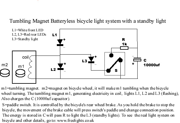
This bicycle safety flashing light system is based on a newly invented electrical generation system that requires no battery and produces no friction on any parts of the bicycle. It generates energy with minimal resistance, making it highly efficient...

Energy Leak Sensor Detector Circuit Diagram. Features: The thermistor value can be selected within the 10K to 22K range at 20°C, allowing for fast detection of energy leaks. The Energy Leak Sensor Detector Circuit is designed to identify and alert...
If you decide to use 2 circuits, I just connect their outputs together...neg output from first circuit to neg output of second circuit & pos output from first circuit to pos output of second circuit. And take readings from...
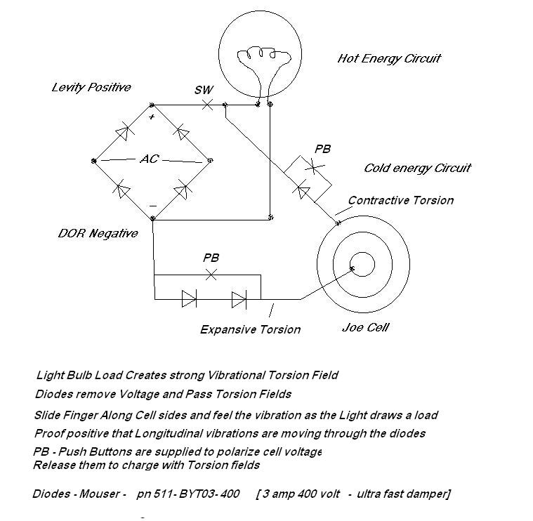
The concept of quadrature involves three manipulable forces rather than the two traditionally considered in electromagnetism. The electric field exhibits both positive and negative voltages, while the magnetic field consists of north and south poles. Additionally, the tempic field...
This sensitive circuit functions as a comparator, detecting minor temperature variations relative to the ambient temperature. It was primarily designed to identify drafts around doors and windows that lead to energy loss, but it can also be utilized in...
This invention is a back EMF permanent electromagnetic motor generator and method that utilizes a regauging process to capture available electromagnetic energy within the system. The device consists of a rotor equipped with magnets of the same polarity, a...