
Energy Leak Sensor Detector

The Energy Leak Sensor Detector Circuit is designed to identify and alert users to potential energy leaks in electrical systems. The core component of this circuit is a thermistor, which is a temperature-sensitive resistor that changes its resistance based on temperature variations. The specified range of 10K to 22K ohms at 20°C provides a balance between sensitivity and stability, ensuring reliable operation across various environmental conditions.
The circuit typically includes a voltage divider configuration where the thermistor is paired with a fixed resistor. This arrangement allows for the measurement of voltage changes that occur when the thermistor's resistance varies due to temperature fluctuations caused by energy leaks. The output voltage from this divider can be fed into a microcontroller or an operational amplifier to process the signal and determine if a leak is present.
Additional components may include a comparator to set a threshold for leak detection, which can trigger an alert or activate a relay to disconnect power in case of a detected leak. A visual indicator, such as an LED, can be incorporated to provide immediate feedback on the operational status of the circuit.
Power supply considerations are crucial, and the circuit may be designed to operate from a low-voltage source, ensuring safety and reducing energy consumption. Overall, the Energy Leak Sensor Detector Circuit is an essential tool for enhancing energy efficiency and preventing potential hazards associated with electrical leaks.Energy Leak Sensor Detector Circuit Diagram. Features: Thermistor value can be chosen in the 10K - 22K @ 20°C range, fast detection of .. 🔗 External reference
Related Circuits
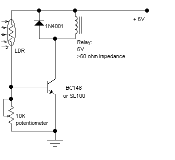
The following circuit illustrates a Light Barrier Sensor Detector Circuit Diagram. Features include a single transistor, an adjustable potentiometer, and a 6V power supply. The Light Barrier Sensor Detector Circuit is designed to detect the presence of an object by...
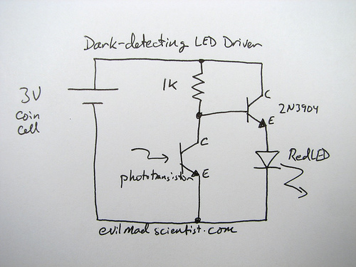
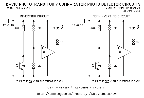
A circuit that uses a phototransistor to create a light-sensitive switch. When there is no light in the room, the LED connected to the phototransistor lights up, and when there is light, the LED turns off. Any schematic or...
During experiments with various receivers and amplifiers powered by "free energy," it was discovered that connecting the audio amplifier to the receiver using only two wires for audio signals and supply voltage is more convenient. This setup allows the...

This circuit was originally designed to detect low water levels in a Christmas tree stand, but it can also be utilized as a water-level detector for pump controls and water sensors in garden and lawn applications. It employs a...
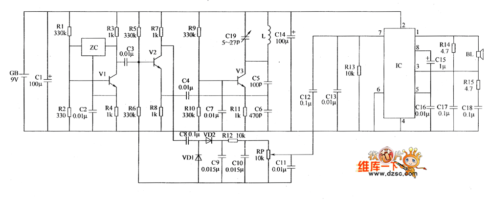
The metal detector circuit includes a fixed frequency oscillator, mixer, detector, detection oscillator, and power amplifier circuit. The fixed frequency oscillator circuit is composed of a ceramic filter (ZC), transistor (V1), resistors (R1 to R4), capacitor (C2), and other...
This page features basic, visible light photo-detector circuits that can be used to detect trains. These methods would normally be used with the photo sensor mounted between the rails. The described photo-detector circuits are designed to detect the presence of...