
Free energy Schematic II
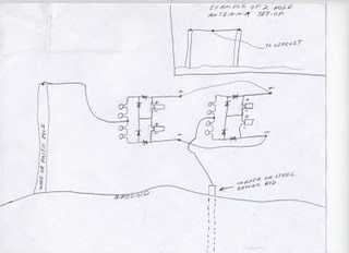
The circuit design involves two identical circuits whose outputs are connected in parallel, facilitating a combined output. The negative output from the first circuit is connected to the negative output of the second circuit, while the positive output from the first circuit connects to the positive output of the second circuit. This configuration allows for simultaneous readings from a common point, which is the junction where the two circuits are interconnected.
A ground wire is taken from the circuit, specifically positioned between two large electrolytic capacitors, ensuring a stable reference point for the circuit's operation. The use of two 100 microfarads polarized electrolytic capacitors provides significant filtering and stabilization of the power supply, which is crucial for maintaining the performance of the circuit.
The circuit also incorporates four ceramic disk capacitors rated at 0.1 microfarads. These capacitors serve as high-frequency bypass components, effectively filtering out noise and ensuring stable operation across the circuit's frequency range.
Four germanium diodes, specifically the 1N34A type, are utilized in the design. These diodes are known for their low forward voltage drop and are suitable for applications requiring high sensitivity. The 1N34A diodes have a peak reverse voltage rating of 75 volts, making them appropriate for various low-power applications. When selecting diodes, it is essential to verify their specifications to ensure compatibility with the intended circuit design.
For sourcing components, the diodes can be found at Mouser Electronics, which provides a reliable supply. Additional resources, such as datasheets and specifications, are available online to assist in confirming the characteristics of the 1N34A diodes and comparing them with other types of germanium diodes. Proper selection and implementation of these components are critical to achieving the desired performance and reliability of the overall circuit.If you decide to use 2 circuits, i just connect their outputs together...neg output from first circuit to neg output of second circuit & pos output from first circuit to pos output of second circuit. And take readings from same place....from where you conected the 2 circuits together. Ground wire connects off of circuit, from inbetween 2 large electrolytic capacitors. 4) .1 micro Farads ceramic disk capacitors 2) 100. micro Farads electrolytic polorized capacitors 4) germanium diodes (1N34A)(mouser# 526-1N34A) diodes can be found here at mouser, these are the one that i use..... http://www.mouser.com/Search/Refine.aspx?Keyword=1n34 i see that there are a few types of germanium diodes out there, the ones i get from mouser are rated at Peek Reverse Voltage 75V here is another website that has good picture of them...but not sure if they are exactly the same ratings.
https://www.micro-tools.com/store/item_detail.aspx?ItemCode=1N34A here is a website that has specifications on some of the differant types... http://www.datasheetcatalog.com/datasheets_pdf/1/N/3/4/1N34A.shtml 🔗 External reference
Related Circuits

The 22-turn coil is positioned above the 84-turn coil. Connecting this coil significantly impacts performance. Testing with a 1 kW heater yielded better results; however, prolonged use may lead to failure. The heater's wire typically does not glow as...
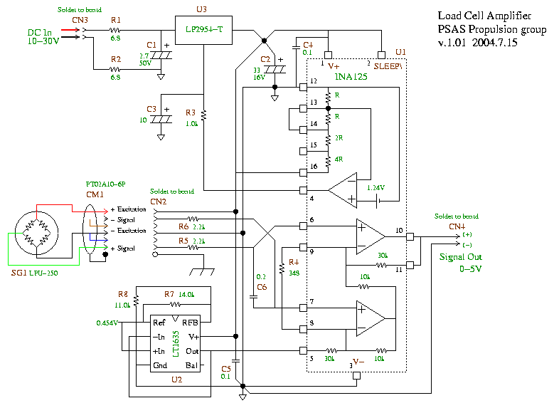
A schematic for a load cell amplifier has been discovered. Load cell amplifiers are typically expensive, with prices ranging from 100 to 300 USD. However, it is possible to build a personal load cell amplifier at a lower cost....
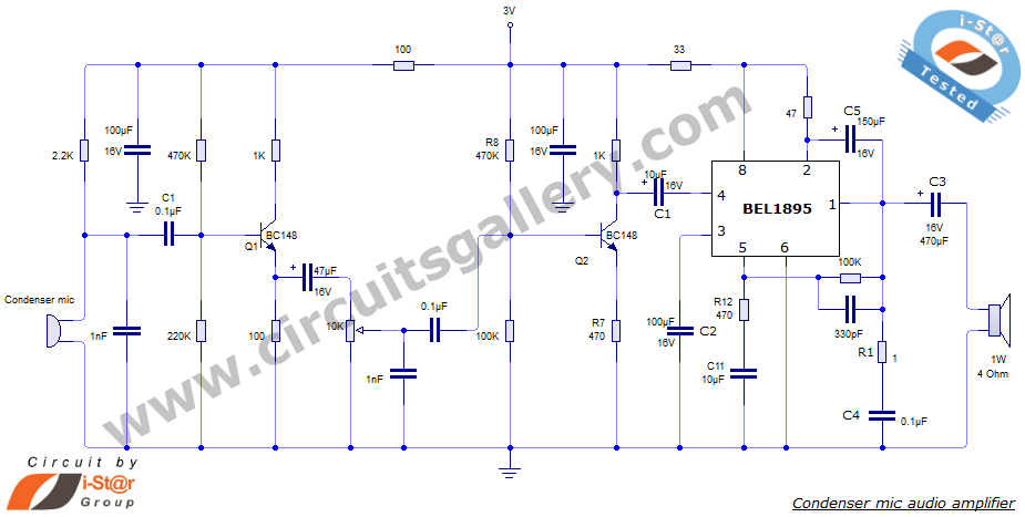
This document presents an audio amplifier circuit suitable for use in walkie-talkies, low-power transmitters, and packet radio receivers. The circuit utilizes a condenser microphone audio amplifier that delivers high-quality audio output of 0.5 watts at 3 volts. The design...
This circuit utilizes a relay to control a water pump, enabling automatic level control for a water reservoir or well. The shorter steel rod acts as the "water high" sensor, while the longer rod serves as the "water low"...
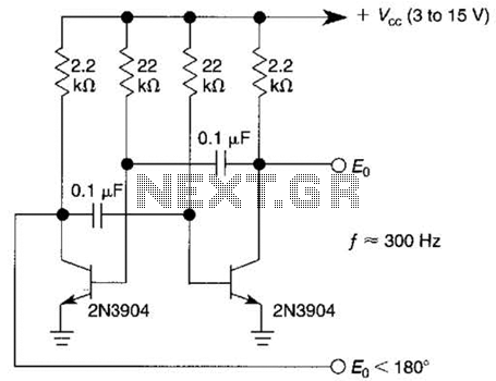
This free-running square-wave oscillator utilizes two NPN transistors. The output frequency is approximately 300 Hz with the specified component values. The circuit operates as a basic oscillator, generating a square wave output through the interaction of two NPN transistors. The...

The following circuit illustrates the Bedside Lamp Timer Circuit utilizing the CD4060 integrated circuit (IC). It operates for 30 minutes, with a blinking LED indicating the last 6 minutes of operation. The Bedside Lamp Timer Circuit is designed to provide...