
LASER BURGLAR ALARM CIRCUIT
The described circuit functions as an intrusion detection system utilizing a laser beam as a sensing mechanism. The primary components include a laser diode as the transmitter, which emits a coherent light beam, and a phototransistor (L14F1) that serves as the receiver. The phototransistor is sensitive to the wavelength of the laser light and is positioned to directly receive the beam.
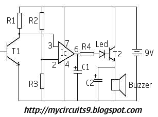
When the laser beam is uninterrupted, the phototransistor remains in a conductive state, allowing a low voltage signal to be sent to the operational amplifier (IC TL071). The operational amplifier is configured to compare the input voltage from the phototransistor against a reference voltage. In the absence of the laser light, for example, when an object crosses the beam, the output of the TL071 transitions to a high state, indicating an alarm condition.
The NPN transistor (Q2) is employed to amplify the output signal from the IC TL071. This amplification is essential to drive a buzzer or alarm system effectively. The buzzer is activated when the transistor is turned on, producing an audible alarm to notify of the intrusion.
For optimal performance, the circuit may require fine-tuning of the reference voltage at the TL071 to ensure sensitivity to the laser interruption. Additionally, the choice of laser and phototransistor should be made based on the operating environment and the required detection range. Overall, this laser-based alarm system presents a reliable solution for security applications, providing a straightforward method for detecting unauthorized access through the interruption of a laser beam.This circuit alarms whenever someone cross the Laser beam transmitted from a LASER. The output of IC TL071 goes high whenever their is no Light(Laser) Ray. This output voltage is further amplified by means of a NPN transistor Q2, which will drive the buzzer and generates an alarm. As i mentioned above, you can use an ordinary Laser as Transmitter and the circuit shown in the figure act as Receiver. The sensing or receivng part of this circuit consisting of a PhotoTransistor L14F1. It will detect Laser Beam and the output is given to IC TL071. Whenever an intruder cross or cuts the ray the circuit alarms. 🔗 External reference
Related Circuits

This car audio amplifier circuit is based on the LA47536 audio amplifier integrated circuit designed by Sanyo. This audio amplifier circuit is specifically designed for car audio power amplifiers. The LA47536 car audio amplifier IC features four output channels...

Common Light Emitting Diodes (LEDs) require a direct current (DC) forward bias of 10 to 20 mA for optimal performance. The maximum allowable DC current typically ranges from 30 to 50 mA. The emitted light color, or wavelength, from...

This circuit serves as a cost-effective alternative to commercially available keying circuits. It has been successfully implemented in the SB-200 amplifier. A schematic of the modified SB-200 is provided. The described circuit is designed to function as a keying mechanism...

The MAX1516 charge pump drives up to 8 white LEDs with constant current regulation to achieve uniform light intensity, capable of delivering up to 30mA per LED for backlighting. The flash group LEDs (LED5 to LED8) are individually controlled,...

This circuit utilizes a pair of Zener diodes to monitor the voltage of a 12-V battery. When the voltage drops below 11 V, diode D1 ceases to conduct, causing pin 3 of flip-flop IC2 to go high. This action...

When the battery voltage is within the range of 7 to 12.6V, the light-emitting diode VLi illuminates, maintaining a consistent brightness. If the battery voltage drops below 7V, VLi begins to emit a red light, and the brightness of...