
simple sound to light converter schematic
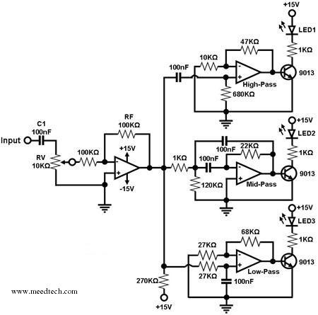
The described circuit serves as an audio signal visualizer, where the audio input is processed through a series of filters that segregate different frequency ranges. The buffer/amplifier stage ensures that the input signal is adequately amplified and buffered to prevent loading effects that could distort the signal. Capacitor C1 acts as a coupling capacitor, allowing AC signals to pass while blocking any DC component, thereby preserving the integrity of the audio signal.
The three filter circuits are designed to isolate specific frequency bands: the low-pass filter allows frequencies below a certain cutoff to pass, the mid-pass filter permits a range of frequencies around a designated center frequency, and the high-pass filter enables frequencies above a certain threshold to pass. Each filter's output is connected to a light-emitting diode (LED) that visually represents the presence of audio energy within its designated frequency range. The choice of resistor values RF and RV1 is critical, as they define the gain of the buffer and the overall response of the filters.
When audio input is received, the circuit responds dynamically; as the amplitude of different frequency components varies, the corresponding LEDs illuminate or extinguish, providing a visual representation of the audio spectrum. This functionality makes the circuit useful for audio analysis, music visualizations, or as a decorative element in audio equipment. The design can be further enhanced by adjusting the filter characteristics or adding more frequency bands for a more detailed visual output.A simple ambit for converting an audio arresting (such as one that comes from the apostle terminals of a CD player). The ambit basically consists of a buffer/amplifier date and three clarify circuits: a high-pass filter, a mid-pass filter, and a low-pass filter.
The achievement of anniversary clarify ambit drives a light-emitting di ode of altered color. The ascribe arresting is fed to the absorber date through C1. The ethics of RF and RV1 should be called so that the absorber is able to drive the three filters absorbed to its output. The low-frequency, mid-frequency, and high-frequency apparatus of the ascribe arresting are alone accustomed to canyon through the low-pass clarify (bottom filter), the mid-pass clarify (middle filter), and the high-pass clarify (topmost filter), respectively, appropriately amid them from anniversary other.
Changes in the achievement of a clarify account its agnate achievement LED to about-face on and off. In effect, agriculture a connected audio arresting to the ascribe of this ambit causes the LED`s to dance`. 🔗 External reference
Related Circuits
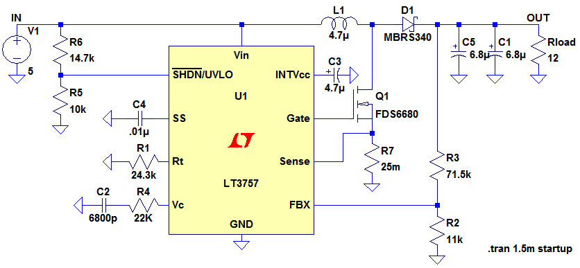
Ignore components C1, C2, R3. The MOSFET, Q1, switches on, creating a short circuit between the right-hand side of the inductor, L1, and ground (0V). A fixed voltage of 3.3V is applied across the inductor, causing its current to...
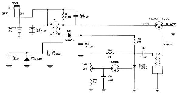
Caution! This strobe light circuit operates on 220V, making measurements and experiments extremely hazardous, even after disconnecting it from the mains. The strobe light circuit is designed to produce high-intensity flashes of light at specified intervals. It typically consists...
This sound-controlled lighting circuit design is utilized to adjust the brightness of connected lights in synchronization with captured sound. The sound-controlled lighting circuit operates by detecting audio signals through a microphone or sound sensor. The circuit typically consists of several...
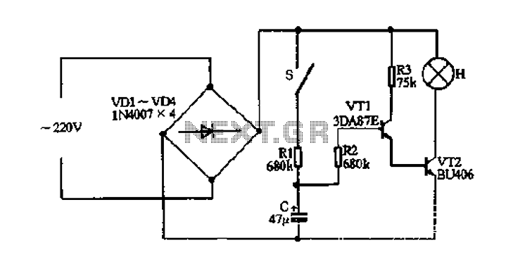
The fade circuit controls the lighting switch depicted in Figure 1-12. The figure illustrates the light switch S, H, which is responsible for lighting. Transistors VT1 and VT2, along with RC components, comprise the fade dimming control circuit. Given...

The circuit employs a field-effect transistor (FET) at the input of a Schmitt trigger, allowing the use of a low-value capacitor. The trigger, controlled by Q1 and O2, exhibits a hysteresis of approximately 3V, regulated by a 3V zener...
Boss MT2 Metal Zone Distortion Pedal Schematic. The MT-2 Metal pedal is one of the most popular guitar pedals, providing over-the-top, insane distortion tones with huge mids and lows and an ultra-saturated sound. The Boss MT-2 Metal Zone Distortion Pedal...