
LM1875 IC For 20Watt Audio Amplifier Circuit
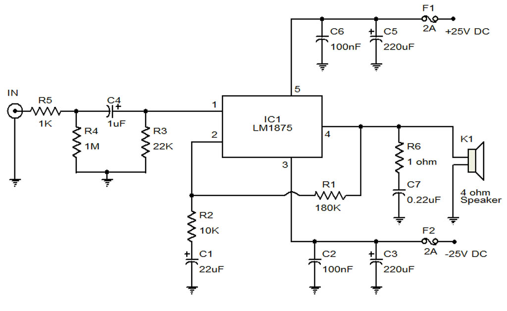
The 20-Watt audio amplifier circuit utilizing the LM1875 IC is a robust solution for automotive sound systems. The LM1875 is a high-performance audio power amplifier capable of delivering up to 20 Watts of output power with low distortion and high efficiency.
The circuit typically includes a power supply section that provides the necessary voltage and current for the LM1875. A common configuration employs a dual power supply, offering ±16V to ±20V, ensuring optimal performance.
Input signals are received through a coupling capacitor, which blocks any DC components while allowing the AC audio signal to pass through to the amplifier. The gain of the amplifier can be set using external resistors, allowing for customization based on specific application needs.
The output stage of the LM1875 connects to a load, such as a speaker, typically rated at 4 to 8 ohms. To protect the circuit from potential damage due to overcurrent or overheating, a heat sink is often mounted on the LM1875, facilitating heat dissipation during operation.
Additional components may include feedback resistors to stabilize the gain and capacitors for filtering and bypassing noise, ensuring high-quality audio output. The circuit can be integrated into a car's audio system, providing enhanced sound reproduction for an improved listening experience.
Overall, this audio amplifier circuit is a practical choice for automotive applications, delivering reliable performance with a straightforward design.The following circuit shows a 20Watt Audio Amplifier Circuit Diagram Based On The LM1875 IC. Features: applied in a car, 20Watt audio amplifier, 4 .. 🔗 External reference
Related Circuits
Today, nearly all computers are equipped with logic blocks designed to implement a USB port. In practice, a USB port can deliver over 100 mA of continuous current at 5V to the peripherals connected to the bus. This capability...
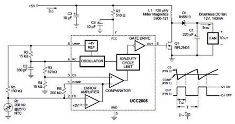
A temperature-controlled pulse-width-modulator (PWM) boost converter circuit diagram is illustrated in the following figure. This boost converter is designed to operate a 12V fan using a 5V supply while maintaining temperature control. The temperature-controlled PWM boost converter circuit operates by...
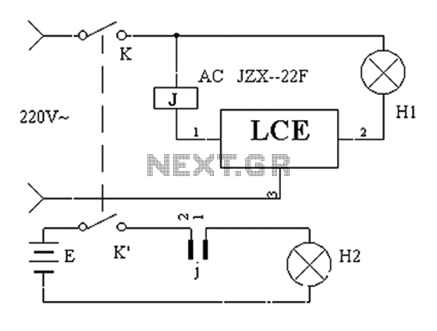
The application circuit operates the device as illustrated below, allowing for intermittent lighting in specific situations (e.g., during surgery). It utilizes an LCE module for blackout emergency lighting, which activates automatically after a power failure, ensuring uninterrupted illumination. In...
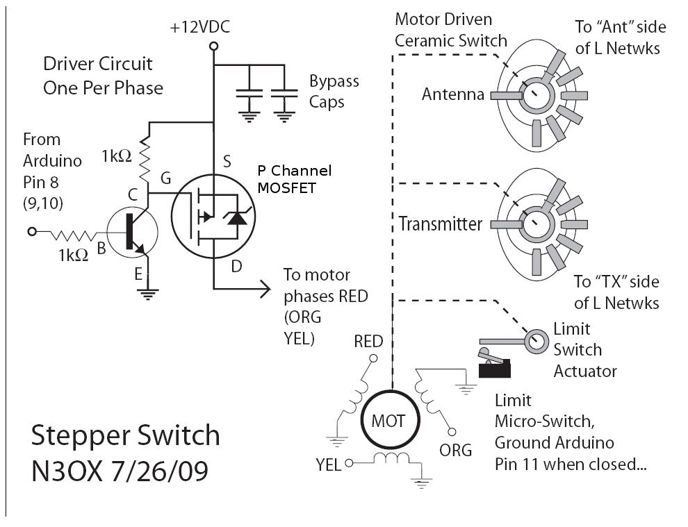
Information is needed regarding a circuit to manage the Remote Coax Ameritron RCS-10, as no diagram can be found on Google. The Ameritron RCS-10 is a remote coax switch designed for amateur radio applications, allowing users to control multiple antennas...
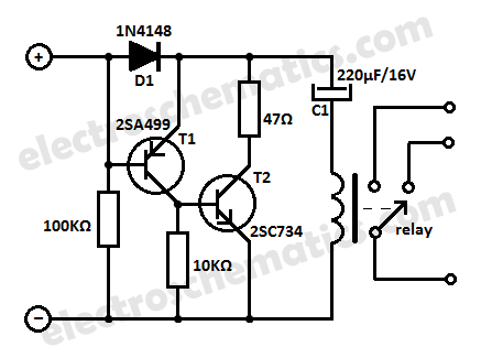
Protect your equipment with this compact 12V time delay relay circuit. The SMPS-based power supply of modern electronic devices is susceptible to voltage spikes. This 12V time delay relay circuit is designed to safeguard sensitive electronic devices by providing a...
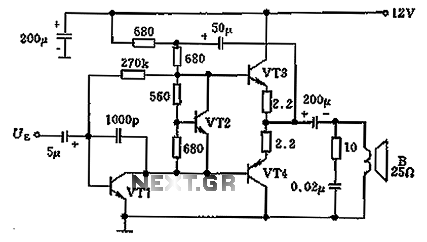
The overload protection circuit operates at a power of 650 mW with a supply voltage of 12 V and is designed for a speaker with an impedance of 25 ohms. The component specifications include: VT1 as transistor NB111EH/J, VT2...
Warning: include(partials/cookie-banner.php): Failed to open stream: Permission denied in /var/www/html/nextgr/view-circuit.php on line 713
Warning: include(): Failed opening 'partials/cookie-banner.php' for inclusion (include_path='.:/usr/share/php') in /var/www/html/nextgr/view-circuit.php on line 713