
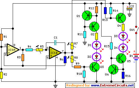
Unity-Gain Four-Input Audio Mixer Circuit

The described circuit operates as a voltage follower configuration, also known as a buffer amplifier. In this setup, the four inputs are connected to a single output, ensuring that the output voltage closely follows the input voltage without amplification or attenuation. The use of 470 kΩ resistors for both the input and feedback paths establishes a unity gain condition, which is critical for applications where signal integrity must be preserved.
In this configuration, each input can be treated as a separate channel, allowing for the simultaneous processing of multiple signals. The high resistance value of the input resistor (470 kΩ) minimizes the loading effect on the preceding stage, making it suitable for interfacing with high-impedance sources. The feedback resistor of the same value ensures that the operational amplifier remains in a stable state, providing consistent performance across all inputs.
The circuit's design emphasizes simplicity and effectiveness, making it ideal for applications in signal conditioning, sensor interfacing, and audio processing where maintaining the original signal level is paramount. The choice of resistors also helps to reduce power consumption while maintaining a high input impedance, which is an essential characteristic in many electronic systems.
Overall, this circuit exemplifies a straightforward yet effective approach to managing multiple input signals with high fidelity and minimal distortion. The circuit has four inputs. The voltage gain between each input and the output is held at unity by the relative values of the 470kH input resistor and the 470kQ feedback resistor. 🔗 External reference
Related Circuits

The RS-232 system connection is faster and easier, but the distance is limited. Therefore, this project involves using an RS-485 system with an RS-232 to RS-485 converter. The RS-232 to RS-485 converter project aims to extend the communication range and...
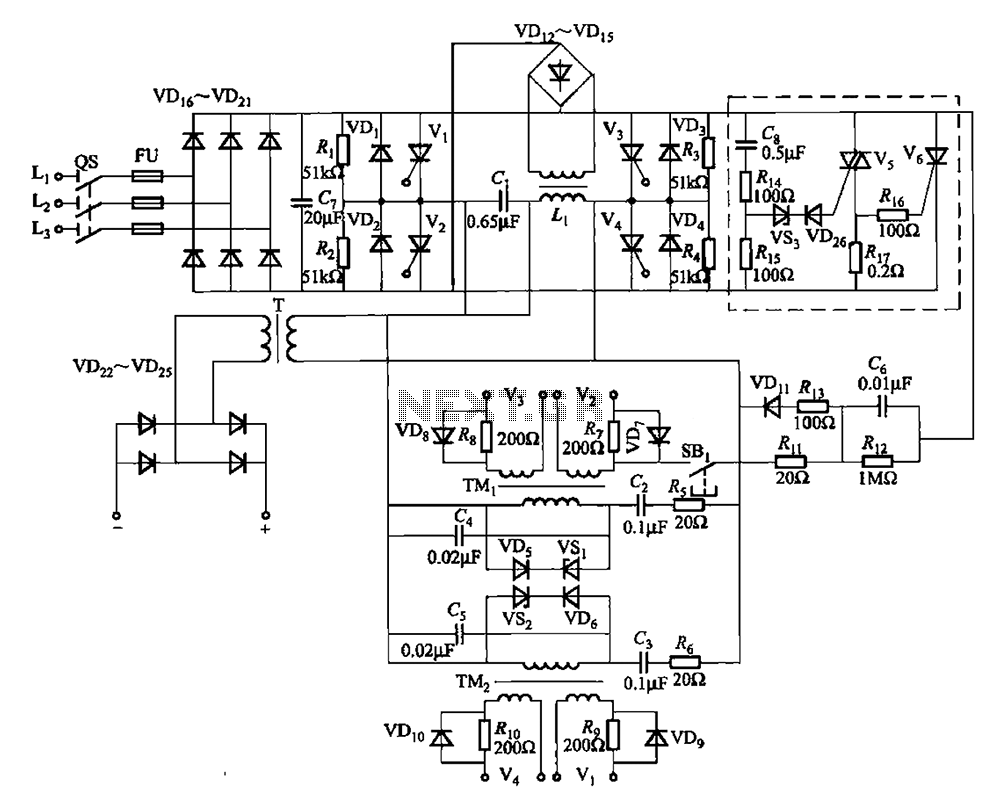
A 25kHz thyristor inverter welding machine circuit utilizes high-frequency operation to enable smaller transformer designs. The circuit diagram is illustrated in Figure 9-14. The no-load output voltage of the machine is 45V DC, with a peak voltage of 90V...
This circuit operates two LED strips in pulsing mode, where one LED strip transitions from an off state to gradually lighting up, then dimming, while the other LED strip performs the opposite action. Each strip can consist of 2...
Tubular xenon lamp power, high brightness, known as the "little sun." Tubular xenon lamp wiring is illustrated in Figure 2-6. The tubular xenon lamp is a high-intensity discharge (HID) light source, characterized by its ability to produce a bright white...

This 4-channel commutator utilizes the 2N4091 to achieve a low channel ON resistance (approximately 30 ohms) and minimal OFF current leakage. The DM7800 voltage translator is a monolithic device that provides gate drive voltages ranging from 10V to 20V...
This circuit below shows a teleremote circuit that enables the switching on and off of appliances through telephone lines. It can be used. The teleremote circuit operates by utilizing telephone lines to control electrical appliances remotely. The primary components of...