
CD4060 Timer Circuit 1 minute to 2 hours
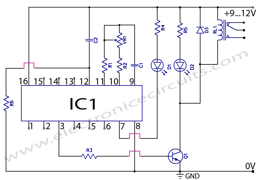
The CD4060 timer circuit is designed to function as a timer switch with a timing range from 1 minute to 2 hours. Central to this circuit is the CD4060 integrated circuit (IC), which incorporates a 14-stage binary ripple counter. This functionality allows for precise timing operations by utilizing an external resistor-capacitor (RC) network to set the timing interval.
The operation of the CD4060 timer begins with the application of power to the circuit. The internal oscillator of the IC generates clock pulses, which are counted by the binary ripple counter stages. The output of these stages can be configured to provide a logic high signal after a predetermined count is reached, effectively controlling an external load, such as a relay or an LED.
To achieve the desired timing range, the values of the resistor and capacitor in the RC network must be selected carefully. The timing period can be calculated using the formula:
\[ T = 2^{(N+1)} \times R \times C \]
where \( T \) is the timing period, \( N \) is the stage number of the counter, \( R \) is the resistance in ohms, and \( C \) is the capacitance in farads. By adjusting these values, the timer can be set to operate within the specified range of 1 minute to 2 hours.
The output configuration can include a transistor or a relay driver circuit to control higher power loads, ensuring that the timer can be used in various applications, including home automation, industrial timing applications, and other electronic projects requiring delayed action.
In summary, the CD4060 timer circuit is a versatile and reliable solution for creating timer functionality with a wide range of timing intervals, leveraging the capabilities of the 14-stage binary ripple counter integrated within the IC. Proper selection of external components is crucial to achieving the desired timing accuracy and performance.CD4060 Timer Circuit 1 minute to 2 hours This is a 1 minute to two-hour timer switch. The 14-stage binary ripple counter Type 4060, IC1, has an.. 🔗 External reference
Related Circuits
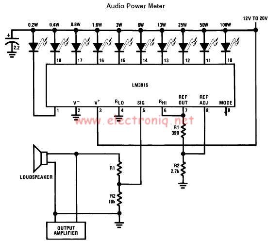
The LM3915 monolithic integrated circuit can be used to design a simple audio power level meter that senses analog voltage levels and drives ten LEDs, LCDs, or vacuum fluorescent displays, providing a logarithmic 3 dB/step analog display. One pin...
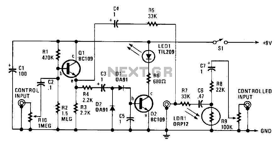
The automatic fader reduces the background music level when narration is in progress. The control input through RIO, a preset audio level control, is directed into an emitter-follower buffer stage (Q1). This buffer provides high input impedance and ensures...
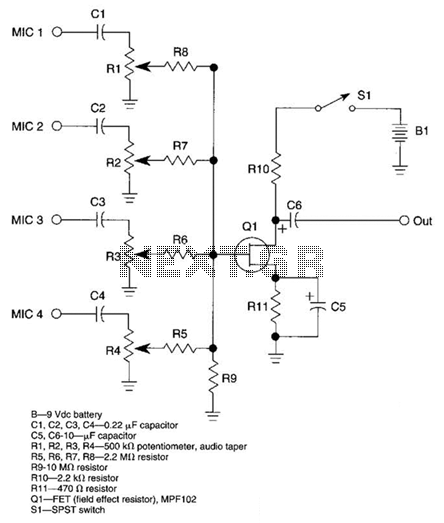
A JFET transistor is utilized as a high-to-low impedance converter and signal mixer. The input impedance is approximately 50.0 kΩ, which can be increased by adjusting resistors R5 to R8 up to 10 MΩ. The output impedance is around...
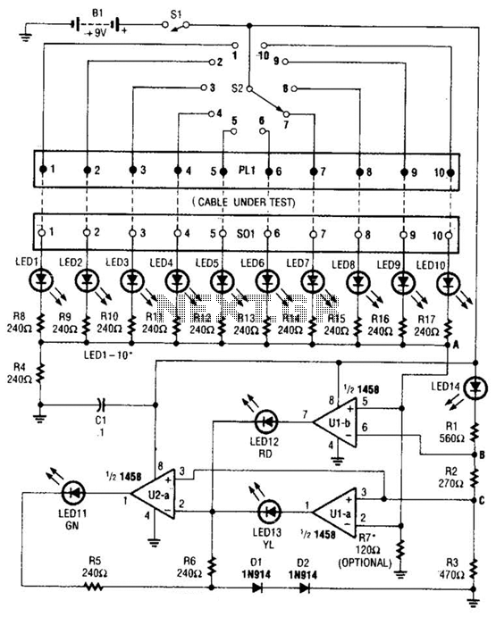
The cable tester utilizes two operational amplifiers (op-amps) configured as window comparators to detect short or open circuit conditions. A third op-amp comparator is employed to indicate a properly functioning circuit, meaning it is neither open nor shorted. Colored...
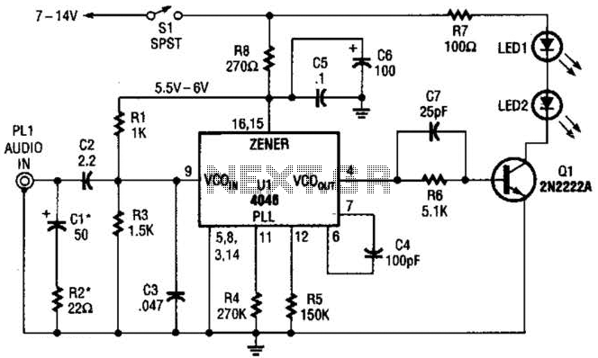
The transmitter for the wireless headphones is constructed using a CD4046 CMOS phase-locked loop, which is paired with a driver transistor and a set of infrared LEDs. While the CD4046 contains two phase comparators, a voltage-controlled oscillator (VCO), a...
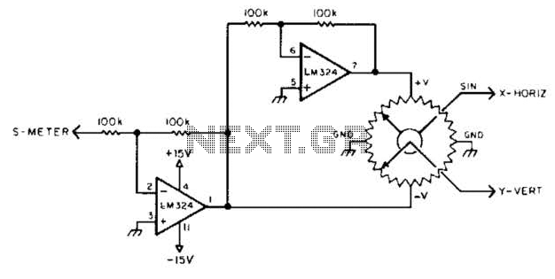
To display polar quantities, which include both the magnitude and direction of a received radio signal, a sine and cosine voltage proportional to an angle corresponding to the antenna direction is required. This setup utilizes a sine-cosine potentiometer connected...