
MAX2653 LNA with Gain-Step Retuned for GPS Applications
The MAX2653 SiGe Low Noise Amplifier (LNA) is specifically designed for RF applications, particularly within the GPS frequency range of 1575 MHz. The architecture of the MAX2653 allows for optimal noise performance, making it suitable for receiving weak signals in environments with high interference. The device operates efficiently at supply voltages ranging from 2.7V to 3.3V, which provides flexibility for various applications.
In high-gain mode, the amplifier can achieve a forward gain of 19.2 dB, with a noise figure of 1.6 dB, demonstrating its capability of amplifying weak signals while maintaining low noise levels. The LNA also features a gain control step of 20 dB, which can be adjusted externally through a single resistor, allowing users to fine-tune the amplifier's performance according to specific application requirements.
The application note highlights the importance of retuning the MAX2653 for optimal performance in the GPS band. By adjusting the matching networks, the amplifier can achieve improved metrics, including an additional 0.5 dB gain, a 0.1 dB reduction in noise figure, and a 2 dB enhancement in IIP3 (Input Third-Order Intercept Point), all while maintaining similar supply current levels.
For applications where a gain step is not necessary, Maxim offers alternative models, the MAX2654 and MAX2655 SiGe LNAs, which provide integrated features such as bias current control and a low shutdown current of 0.1 µA. These devices simplify design requirements by incorporating output matching to 50 Ω, making them suitable for direct connection to standard RF systems.
The evaluation of the MAX2653 after component modifications on the evaluation kit yielded significant performance data. The results, as referenced in Table 2, provide a clear understanding of the amplifier's capabilities when retuned for the GPS band. It is critical to consider the slight losses incurred at the input and output stages, estimated at approximately 0.2 dB each, when interpreting the performance metrics. This ensures an accurate representation of the amplifier’s operational characteristics, including the effective noise figure and gain values, which are pivotal for system-level design and analysis. Further detailed performance data across various frequencies can be found in Table 3, providing comprehensive insights into the amplifier's behavior in diverse operational scenarios.This application note presents alternate RF matching networks for the MAX2653 SiGe LNA, tuned for the GPS band (1575MHz center frequency). Performance metrics (supply current, forward gain, NF, IIP3, reverse isolation and input/output return loss) for both high and low gain modes, as well as 2.
7V and 3. 0V supplies are provided. For VCC = 2. 7V, high-gain mode, this application provides 19. 2dB Gain, 1. 6dB NF, and The MAX2653 SiGe Low Noise Amplifier (LNA) is internally optimized for lowest noise performance in the US PCS (1930MHz to 1990MHz) and the European DCS (1805MHz to 1880MHz) receive bands. These LNAs offer a 20dB gain control step, externally adjustable gain and linearity (via single external resistor), 2.
7V to 3. 3V operation, and a 0. 25 µA shutdown mode. Maxim does not offer a stand-alone LNA for the GPS (1575MHz center) band that includes a gain-step, but re-tuning the MAX2653 to this lower band offers a excellent solution. These alternative matching values (Table 1) offer 0. 5dB more gain, 0. 1dB better noise figure, and 2dB better IIP3 - all for nearly identical supply current. For applications that do not require a gain step, Maxim offers the MAX2654 and MAX2655 SiGe GPS LNAs.
They offer a bias current control (via external resistor) to set gain and linearity, a 0. 1 µA shutdown mode and integrated 50 © output matching. Find the datasheet at. After replacing the matching components on the EVKit, key performance metrics were re-tested at room temperature ”Table 2 provides the results of the re-tuned MAX2653 bench testing. These values are referred to the EVKit SMA connectors; to get values referred to the output of the matching networks, assume approximately 0.
2dB loss at each the output and the input. In this fashion, the NF of the circuit is actually about 1. 57dB, gain is about 19. 2dB, and so on. Additional Gain and NF data over frequency is provided in Table 3. 🔗 External reference
Related Circuits
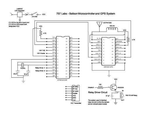
The balloon reached a peak altitude of 103,258 feet. Several factors needed to be considered when launching a payload to this height. Unlike creating an electronics package for sea level, variables such as air pressure, temperature, relative humidity, and...
The project originated from a request by Tony Bowler, a member of the Long Eaton Club, who sought assistance in converting a "Golden Oldie" model to electric free-flight. He selected Vic Smeed's "Debutante" to be powered by seven AE...
Following last year's rediscovery of radio-controlled flight, there is a growing interest in the hacking and modification potential of the budget-friendly 9-channel FlySky FS-TH9X transmitter (also marketed as Turnigy/Eurgle, etc.). The original 2.4GHz RF module and firmware are quite...
The Yaesu FT-7900E radio's power status can be utilized to manage the power status of the GPS and Tracker without requiring additional cabling. If implemented correctly, this would enable the radio's Auto-Power-Off feature to also turn off the GPS...
This two-stage design utilizes enhancement-mode pHEMT device technology to support IEEE 802.11a, HiperLAN2, and HiSWANa local-area network receivers. The two-stage design is characterized by its use of enhancement-mode pHEMT (pseudomorphic High Electron Mobility Transistor) technology, which is essential for achieving...
Power demand in portable designs can require, in specific applications, more than 1 A. A method involves paralleling two DC to DC converters on the same load instead of using a single higher current converter with a lower switching...