
Maze Solving Robot using a PIC18F2525 Microcontroller Project
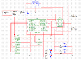
The robot's design incorporates several key components to achieve its objectives. The PIC18F2525 microcontroller serves as the central processing unit, managing the inputs from the sensors and controlling the motors based on the defined states. The choice of analog sensors enhances performance by simplifying the coding requirements and allowing for quick detection of line positions. The H driver is responsible for controlling the motors, enabling precise movements in response to sensor inputs. The use of four sensors allows for comprehensive coverage of the robot's front, facilitating accurate line following and decision-making at intersections.
The power supply configuration, utilizing four AA batteries, provides the necessary voltage for operation while ensuring portability. The 5-volt regulator stabilizes the power supply to the microcontroller and other components, ensuring reliable performance. The robot's state machine logic, prioritized in a defined order, allows for efficient navigation through the maze, with the ability to react dynamically to changing conditions.
In conclusion, the robot's design and functionality are well-aligned with the project goals, allowing it to effectively navigate complex mazes while adhering to the specified constraints. The implementation of state management, sensor feedback, and power regulation contributes to the overall success of the project.The goal of the project is to create a robot that will follow a black line on a white sheet of paper and solve a maze created out of those materials. The project also included a list of specifications that were to be followed. These specifications are: The maze will have black lines, 1/4 to of an inch in width on white paper The maze will be
no larger than 10x10 feet. All paths meet at 90 degree angles Dead ends and loops possible Robot must fit in a 6x6 inch square Must be able to operate without a power cord Designed to finish a maze in the fastest possible time. Choose PIC18F2525 because it has multiple CCPs to allow for multiple pulse width modulators, it has _ analog inputs in case they were needed, it is compatible with the compiler software on our computer, didn`t care about a very fast clock speed Used analog sensors because they can be used as digital sensors and require less code to implement.
The sensors used include the emitter and the receiver as one part (didn`t have to worry about the emitter and receiver working together). A switch is used to turn the robot on or off. When it is on it is connected to a power supply of 4 AA batteries with 1. 5 volts each for a total of 6 volts, this is considered the unregulated power. Unregulated power goes to a 5 volt regulator. Regulated power runs to the PIC, the H driver, the RJ11, and the 4 sensors. Unregulated power runs to the H driver as well. The robot decides its direction based off of the outputs of the four sensors. The robot has 4 different states, and they are: Forward, Left, Right, and Turn Around. The state priority is in this order: Left, Forward, Right, and, lastly, Turn Around. The four sensors are placed close together at the front of the robot. Each sensor has a corresponding LED that lights up when the sensor is high. The left and right sensors are slightly farther back then the front two sensors and the front sensors are centered and side by side.
The robot enters the Left state whenever the left sensor goes high until the front two sensors go high. When the two center sensors are high and the left sensor is low, the robot enters the Forward state. If neither of the previous conditions are true and the right sensor is high, then the robot enters the Right state until the front two sensors go high.
If none of the sensors are high, then the robot enters the Turn Around state where it does a 180o right turn in place. With the 4 previously mentioned states our robot is able to make turns, turn around from dead ends, correct itself on straight lines, and create random turns that ignore the left turn priority.
The robot is able to do the second 2 mentioned abilities because of the positioning of the sensors. By having the left and right sensors extremely close to the front sensors, the robot is able to make very small left and right turns to keep itself on a straight line. The robot is able to randomly ignore state priority because of while loops used in the code. For example, the motor is coming to a 3 way intersection with left and straight directions in front of it.
Under normal priority the robot should turn left at the intersection. When the robot approaches the intersection it may be caught in the Right state in order to correct itself on the straight line. The robot exits the Right state once the front 2 sensors have gone high, so there is a possibility that the robot is in the Right state as it enters the intersection.
If this is true, the left sensor will be ignored until the front sensors go high and the robot will go through the intersection straight because the left option was ignored. By being able to stay on the lines of the maze, follow turns, turnaround, and provide occasional random turn priority, the robot should be able to find its way through any maze eventually even if there are loops within the maze.
Overall, the final design worked as intended. However, several different ver 🔗 External reference
Related Circuits
Raspbian on the Raspberry Pi is excellent, but the official image is large and includes various components that are not needed. The devices typically do not have screens, as they are used for playing music, functioning as GPS NTP...
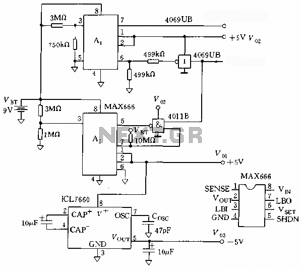
The microprocessor utilizes a linear regulator power circuit that is constructed using two MAX666 devices. The power supply for the CPU and A/D converter is connected to A2, while the RAM and real-time clock receive power from A1. The...
This standalone digital thermometer regulates the temperature of a device based on its requirements. It displays the temperature on four 7-segment displays, with a range from 55 to +125 °C. The core of the circuit is the AT89S52 microcontroller,...
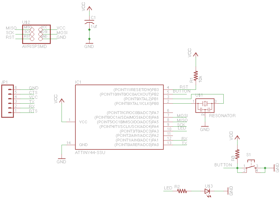
For this week's assignment, a chip design was provided, and the task was to incorporate a button and an LED (light-emitting diode). The objective was to fabricate the chip and program it to interact with the light and button....
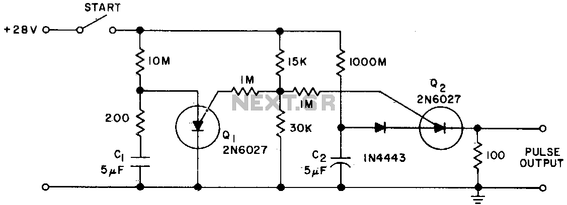
The Programmable Unijunction Transistor (PUT) serves as both a timing element and a sampling oscillator. A low leakage film capacitor is required for capacitor C2 because of the minimal current supplied to it. The Programmable Unijunction Transistor (PUT) is a...
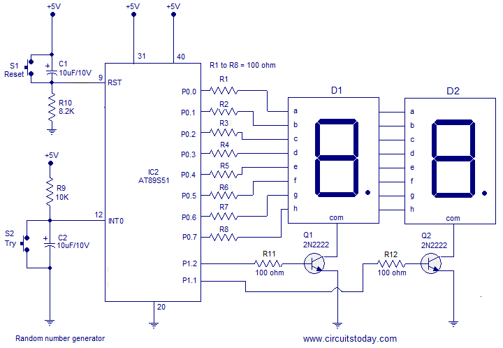
A simple random number generator utilizing the 8051 microcontroller. The AT89S51 is the controller employed in this setup. The circuit design for the random number generator based on the AT89S51 microcontroller involves several essential components and connections. The AT89S51 microcontroller,...