
MCU system Controller 12V DC Motor Speed and Direction using IRF150
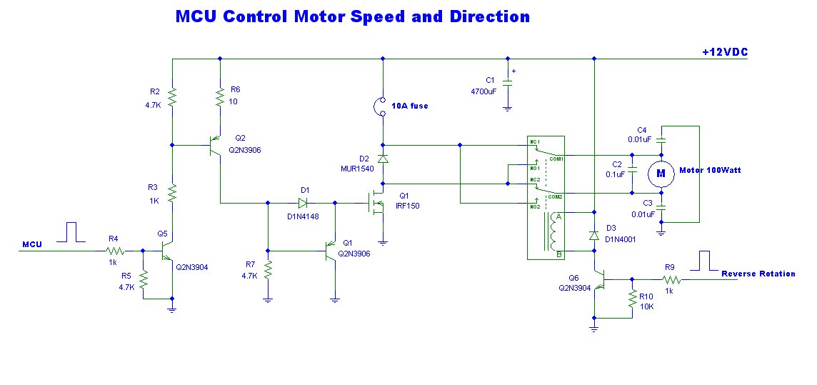
The power motor controller circuit functions by integrating a 12V power supply with a microcontroller that manages the operation of the motor. The MCU receives input signals, which dictate the desired direction of the motor. When the MCU is activated, it outputs a control signal, typically a PWM (Pulse Width Modulation) signal, to power transistors or MOSFETs that act as switches for the motor.
The circuit may include additional components such as diodes for flyback protection, capacitors for filtering, and resistors for current limiting. The use of high-quality components ensures reliability and efficiency in motor operation. The design should also consider heat dissipation, especially in the switching components, to prevent overheating during prolonged use.
To control the motor's direction, the MCU can be programmed to switch the polarity of the voltage applied to the motor terminals, allowing for forward and reverse motion. The circuit may also incorporate feedback mechanisms, such as encoders, to provide real-time data on motor position and speed, enhancing control precision.
In summary, this power motor controller circuit provides a robust solution for controlling 12V motors, with the capability of forward and backward movement, managed by a microcontroller for precise operation.This be power motor controller 12V circuit. with a signal MCU Control be high class voltage , about 3V. It can motor control turn advance or walk go backwards. 🔗 External reference
Related Circuits

The circuit operates a small motor for opening and closing a pair of curtains. The DC motor consists of six basic components: commutator, stator, rotor (also known as armature), axle, field magnet(s), and brushes. Key components include LED, diode,...
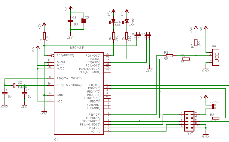
To program an AVR microcontroller using a USB port instead of parallel or serial interfaces, USBasp is the most suitable option. A circuit diagram for USBasp is available. The procedure for burning the hex file includes installing avrdude (WinAVR),...
The circuit is designed to operate with an external power supply, which is why it does not include a transformer, rectifier, or filter capacitors in the schematic. However, these components can be added if desired. To utilize the circuit,...
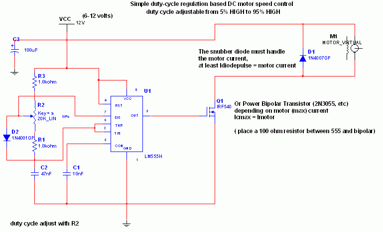
The 555 IC is configured as an astable multivibrator, producing a constant frequency independent of the duty cycle. The total resistance (R_charge + R_discharge, with the diode in consideration) remains constant at 22 kΩ, resulting in a frequency of...
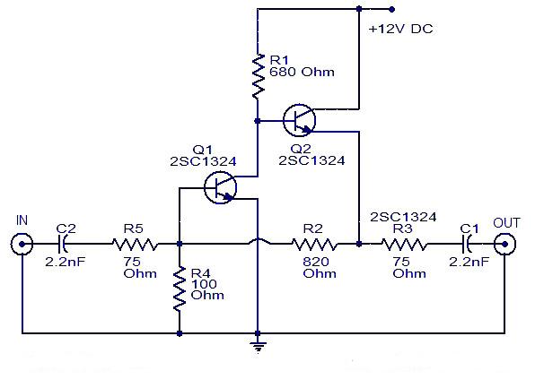
This is a cable TV amplifier utilizing two transistors. The amplifier circuit is designed for cable TV systems using 75 Ohm coaxial cables and operates effectively up to 150 MHz. Transistor T1 is responsible for amplification, providing an expected...
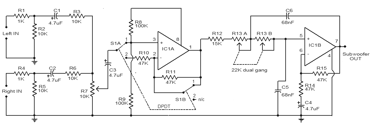
This is a simple subwoofer filter circuit that can be powered by a 12V DC source. It is particularly useful in automotive applications for subwoofers. The circuit functions as a low-pass filter, with a pass frequency adjustable between 60...
Warning: include(partials/cookie-banner.php): Failed to open stream: Permission denied in /var/www/html/nextgr/view-circuit.php on line 713
Warning: include(): Failed opening 'partials/cookie-banner.php' for inclusion (include_path='.:/usr/share/php') in /var/www/html/nextgr/view-circuit.php on line 713