
measuring battery capacity with an arduino
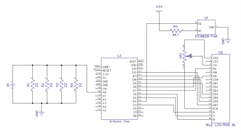
A comprehensive electronic schematic can be developed based on the described circuit. The primary components include an Arduino microcontroller, an LCD display, and a resistive load configured from multiple resistors. The Arduino serves as the central processing unit, responsible for controlling the measurement process and displaying results. The LCD panel provides a visual interface for real-time data readouts, including voltage, temperature, and cumulative energy.
The resistive load is critical for the energy measurement process. By employing four 22-ohm resistors in parallel, the total resistance is effectively reduced to 5.5 ohms. This configuration allows for a consistent discharge rate, enabling accurate energy calculations. The circuit is designed to monitor the voltage across this load continuously; when the voltage drops below the 0.2V threshold, the measurements cease, and the total energy output is displayed.
Powering the circuit through a USB connection or a DC jack ensures that the energy from the battery is fully utilized by the load, providing a clear assessment of the battery's performance. The Arduino is programmed to initiate data collection upon detecting a battery connection, logging voltage and temperature readings at one-second intervals. The logging feature allows for external data capture via a USB port, facilitating further analysis of the battery performance.
This experimental setup provides a relative comparison of various AA battery brands based on their energy output and cost-effectiveness, allowing users to make informed decisions based on the cost per Watt-Hour metric. The methodology emphasizes practical energy measurement rather than scientific precision, catering to users seeking a straightforward evaluation of battery performance.I needed a couple of AA batteries and found the display at the supermarket where they were all arrayed. Normally when I`m shopping in the supermarket, I tend to look at the price/kg or price/l when comparing similar products.
In the case of the batteries, there was no such indicator. Fine, I thought, I`ll work it out myself. I grabbed a few differ ent makes and scanned the packaging for some measure of their capacity. Nothing. Not a single one of the batteries had any indicator of how much energy they would provide. Instead, they all had terms like PLUS`, SUPER`, ULTRA` and of course had wildly differing prices. So, I decided that it was time for an experiment and bought one pack of every type I could find. My idea was really simple: I would make a circuit that would fully discharge each of the batteries while measuring how much energy it produced (displayed in Joules and in Watt-Hours. I had an Arduino and an LCD panel left over from a different project so I thought I`d make a standalone unit.
As the design evolved, I let two additional features creep in: Note: This was never intended to be a scientific instrument to measure how long a battery would power your circuit - it`s designed to provide a relative comparison of different batteries using a similar load. The circuit works by measuring the voltage across a fixed load every second until the voltage drops to less than 0.
2V. For simplicity, I used a resistive load (the original plan was to use a 4. 7R resistor but I didn`t have any high power resistors to hand so I used 4 22R resistors in parallel instead giving me an effective load of 5. 5R. Here`s the final circuit: This case from adafruit ended up being perfect because it already has cutouts and standoffs for the arduino and the LCD.
All that was left was to add a little bit of stripboard to hold the extra components. Note that the whole circuit is powered from the USB connection (or the DC jack) - all the power from the battery is consumed by the load resistors. When the unit resets, it waits until a battery is connected before starting any measurements. Once it detects a battery, it measures the temperature and voltage once a second and displays the cumulative energy in Joules and Watt-Hours on the display.
It also logs the readings to the USB port once per second. You can capture these to a text file with any terminal emulator but I found the easiest thing to do was to use screen: Once the voltage drops below 0. 2V, it will stop measuring and display the total energy produced. If you`re using screen to capture the data, quit it with K and rename the logfile to something more memorable: So far, I`ve captured the data from 10 brands of alkaline battery.
In each case, I took 1 battery from the pack and measured its capacity. Obviously, it would be better to take a selection of each and average the results but I didn`t want to waste all my batteries on the test. In most cases, I bought the batteries in packs of 4. It`s interesting to take the cost of each battery (pack cost / pack size) and combine that with the measured capacity: This lets us compare each of the batteries in terms of the cost per Watt-Hour (which is really all you should care about when buying them).
Obviously, lower is better: 🔗 External reference
Related Circuits
Often, there are instances where it becomes necessary to wind a coil for a project or to identify an unmarked coil found in a collection. To determine its inductance, an oscilloscope can be utilized. A resonant circuit can be...

This type of charger transfers RF energy from an inductor (L2) to an external pickup coil. The pickup coil is connected to a rectifier and a battery that requires charging. This design is advantageous as it eliminates the need...
Switch mode circuits can implement a lead acid battery charger more efficiently. It can be constructed using the bq24105 battery charger controller. Switch mode power supplies (SMPS) are widely recognized for their efficiency and compactness, making them suitable for applications...
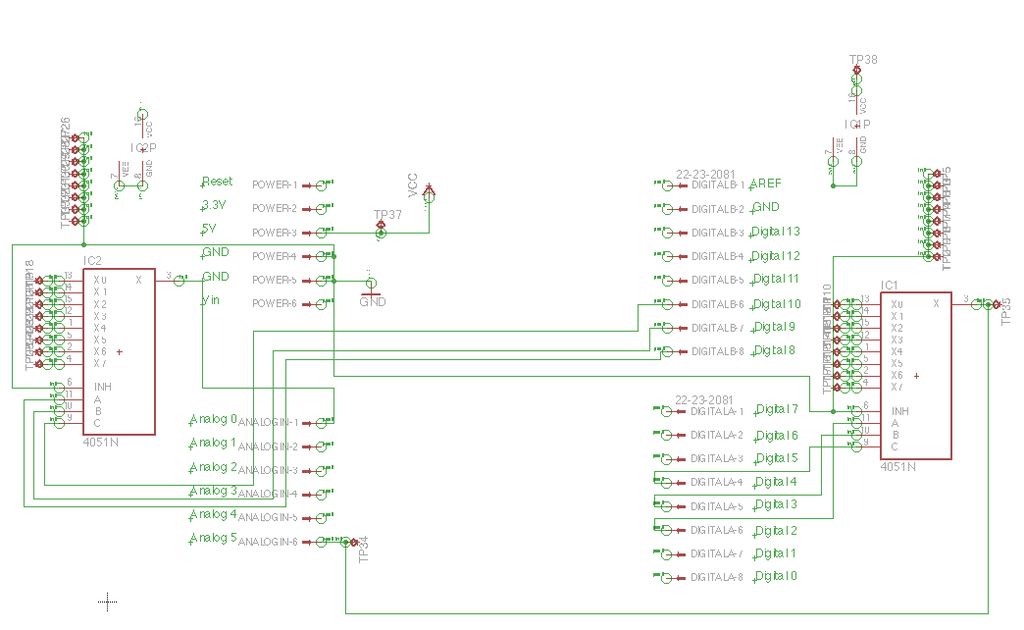
Inspired by a previous project, a unique design was developed that incorporates an umbrella capable of playing musical notes when pressed. For additional information regarding the 4051 chip, which functions as a multiplexer or demultiplexer, refer to resources available...
Battery eliminators are circuits that create a DC power supply from AC mains. Essentially, battery eliminator circuits consist of a step-down transformer, rectifier, and voltage regulator. A simple circuit of a multipurpose battery eliminator features various output voltage ranges...
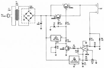
The charger's output voltage is adjustable and regulated, featuring an adjustable constant-current charging circuit that is compatible with most NiCad batteries. It is capable of charging a single cell or multiple series-connected cells with a maximum voltage of 18V....