
universal battery charger
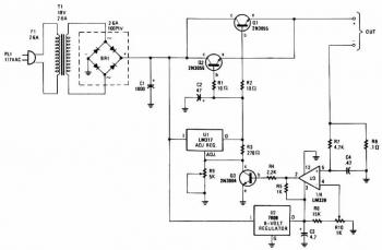
The described charger circuit employs a robust architecture that effectively manages the charging process for NiCad batteries. The adjustable output voltage feature allows flexibility in charging different battery configurations, accommodating both single cells and series arrangements up to 18V. The use of power transistors Q1 and Q2 as series regulators is pivotal for maintaining a stable output voltage, ensuring that the charger adapts to varying load conditions without compromising performance.
The LM-317 voltage regulator plays a crucial role in this design, providing a precise and adjustable voltage reference that governs the base drive of the power transistors. The incorporation of potentiometer R9 allows for fine-tuning of the output voltage, enabling users to set the charger according to the specific requirements of the battery being charged.
The current sampling mechanism utilizing resistor R8 is an essential component for monitoring the charging current. By generating a voltage proportional to the current flowing through it, R8 provides real-time feedback to comparator U3. This feedback is critical for implementing a closed-loop control system that adjusts the charging current dynamically. The comparator's operation ensures that as the battery reaches its charge voltage, the current is reduced, preventing overcharging and extending the battery's lifespan.
The interaction between R8, U3, and Q3 creates a self-regulating system that enhances the reliability of the charger. As the battery voltage rises and the current decreases, the feedback loop effectively turns off transistor Q3, thereby reducing the charging current to a safe level. This intelligent regulation mechanism is vital for maintaining the health and efficiency of NiCad batteries during the charging process. Overall, this charger design exemplifies a practical application of electronic components in battery management systems, ensuring optimal performance and safety.The charger`s output voltage is adjustable and regulated, and has an adjustable constant-current charging circuit that makes it easy to use with most NiCad batteries. The charger can charge a single cell or a number of series-connected cells up to a maximum of 18V. Power transistors Q1 and Q2 are connected as series regulators to control the batte ry charger `s output voltage and charge-current rate. An LM-317 adjustable voltage regulator supplies the drive signal to the bases of power transistor Q1 and Q2. Potensiometer R9 sets the output-voltage level. A current sampling resistor, R8 (a 0. 1 ohm/5W unit), is connected between the negative output lead and circuit ground. For each amp of charging current that flows through R8, a 100mV output is developed across it. The voltage developed across R8 is fed to one input of comparator U3. The other input of the comparator is connected to variable resistor R10. As the charging voltage across the battery begins to drop, the current through R8 decrease. Then the voltage feeding pin 5 of U3 decreases, and the comparator output follows, turning Q3 back off, which completes the signal`s circular path to regulate the battery`s charging current.
🔗 External reference
Related Circuits
Most individuals are unaware that there are typically over a dozen battery backup systems present in their homes. The average American has around 18 battery-backed devices in their household. These battery backup systems protect crucial, expensive, or portable electronics...
This circuit functions as a night lamp when a wall mains socket is unavailable for plugging in a continuously operating small neon lamp device. To minimize battery consumption, it utilizes a single 1.5V cell, and a simple voltage doubler...
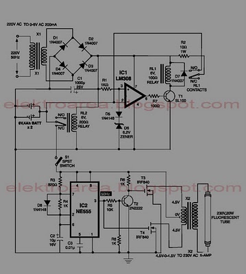
This circuit is an IC-controlled emergency light system. It automatically switches on the light during a mains failure and includes a battery charger with overcharge protection. When the mains power is absent, relay RL2 is in a de-energized state,...
Tests 1.5 to 15 Volt cells. This circuit runs a fast battery test without the need of power supply or expensive moving-coil voltmeters. It features two ranges: when SW1 is set as shown in the circuit diagram, the device...
Flying hand launch gliders necessitate the use of small-capacity receiver NiCad battery packs. While these lightweight packs are advantageous, they have the significant drawback of quickly depleting. Although careful timing of flights can be employed, it often results in...
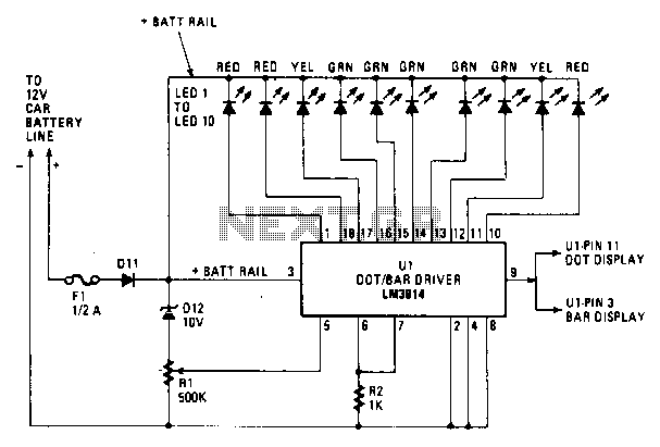
Most of the circuitry is contained in the LM3914 dot/bar-graph driver IC chip. In addition to the comparator circuitry within the package, it also contains a stable reference supply and the drivers for the LEDs. Resistor R2 acts as...
Warning: include(partials/cookie-banner.php): Failed to open stream: Permission denied in /var/www/html/nextgr/view-circuit.php on line 713
Warning: include(): Failed opening 'partials/cookie-banner.php' for inclusion (include_path='.:/usr/share/php') in /var/www/html/nextgr/view-circuit.php on line 713