
Output 12V-10A power circuit
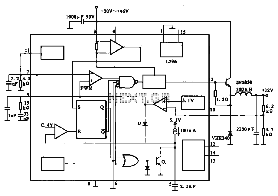
The 12V-10A power circuit is designed to provide a stable and efficient power supply suitable for various applications that require significant current output. Central to this design is the L296 integrated circuit, which is a high-performance voltage regulator capable of delivering high current levels while maintaining low output voltage ripple.
The circuit typically includes input capacitors to filter voltage spikes and ensure stable operation. A transformer may be used to step down the AC voltage to a suitable level before rectification. The rectification stage generally employs a bridge rectifier configuration, converting AC voltage to DC. Following this, additional filtering capacitors are implemented to smooth the rectified output, reducing ripple voltage and providing a stable DC voltage.
The L296 operates by switching on and off rapidly, regulating the output voltage through pulse-width modulation (PWM). This method enhances efficiency, reducing heat generation compared to linear regulators. The output stage may include additional components such as output capacitors to further stabilize the voltage and protect against load transients.
Thermal management is crucial in high-current applications; therefore, appropriate heat sinks should be used with the L296 to dissipate heat effectively. Furthermore, the circuit design should incorporate overcurrent protection mechanisms to prevent damage to the components during fault conditions.
Overall, this power circuit is characterized by its compact size and efficiency, making it suitable for applications in robotics, automotive systems, and other electronic devices requiring robust power supply solutions.Output 12V-10A power circuit +12 V is the use of high-current switching power supply circuit consisting of L296, the output current up to 10 A. The entire circuit is small, seldom-used components.
Related Circuits
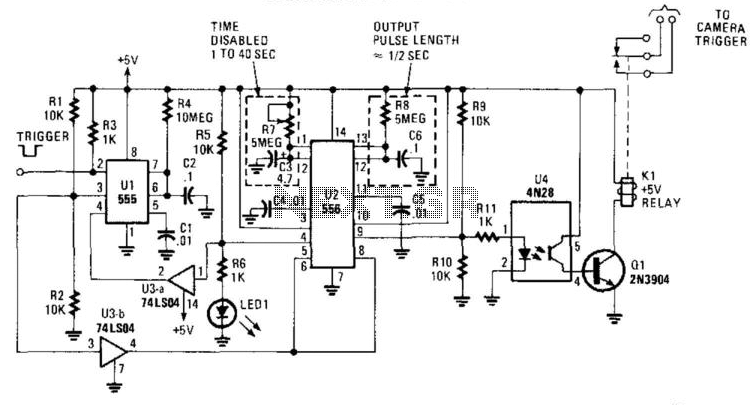
This circuit is designed to activate a camera shutter. Grounding pin 2 of U1 causes pin 4 of U1 to go high, which triggers both timers of the dual timer U1. One output maintains the reset (pin 4) of...
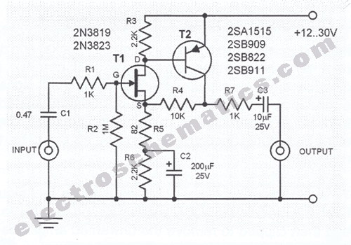
In the first circuit, the BC548 transistor is configured as a Colpitts oscillator, with the frequency being adjusted through the use of a crystal. A high-quality crystal will produce high-frequency oscillations, and the output at the collector is rectified...
The liquid level controller circuit comprises a power supply circuit and a level detection control circuit, as illustrated in the accompanying chart. The power supply circuit includes a power switch (S1), a power transformer (T), bridge rectifiers (UR1, UR2),...
This microphone preamplifier utilizes the low-noise integrated circuit uA739. The circuit serves as an example of an effective preamplifier design for dynamic microphones. The integrated circuit contains two identical preamplifier circuits, with the second preamp functioning in the same...
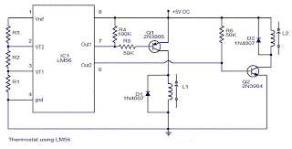
The values of the LM56 thermostat project circuit diagram for resistors R1, R2, and R3 at the travel points VT1 and VT2 can be determined using the following equations. This electronic circuit thermostat with the IC LM56 serves as...
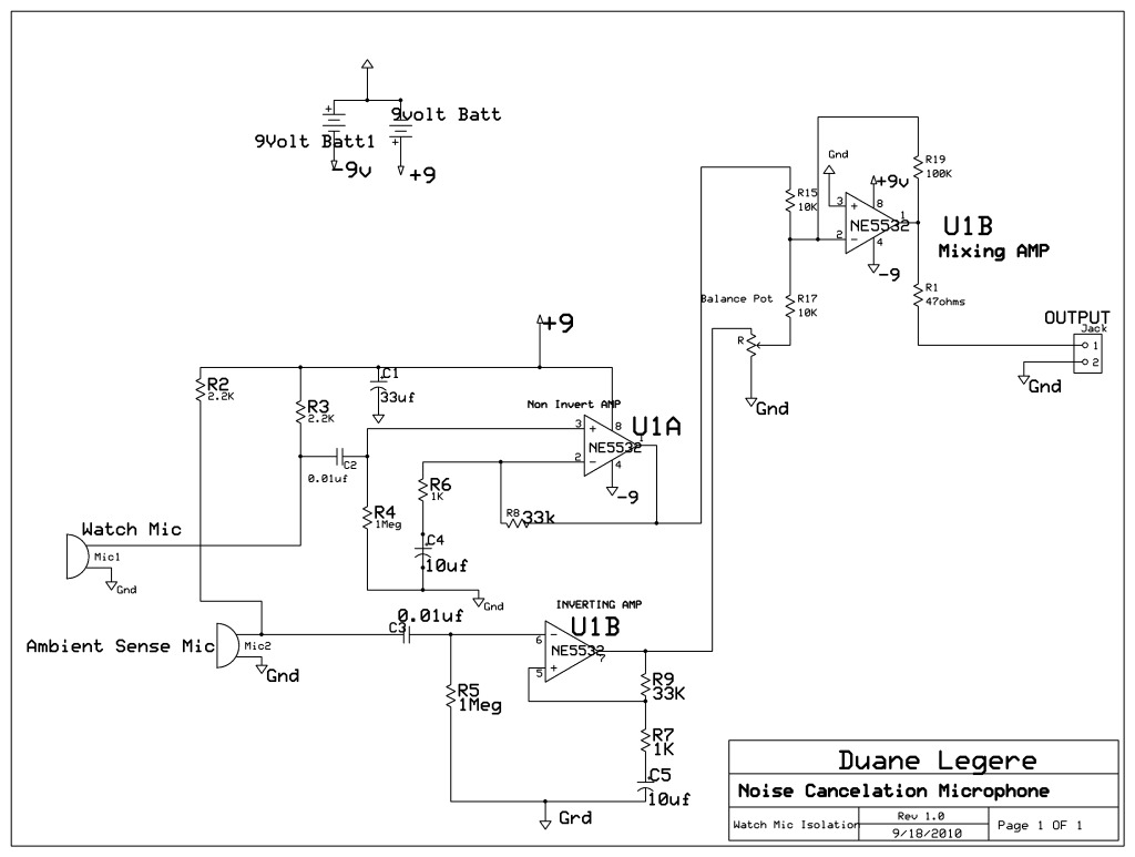
A microphone is designed to listen to a wristwatch while canceling ambient noise in the room. A circuit has been included, which is based on a headphone cancellation circuit. The schematic will be provided shortly. The suggested approach is...