
WWV receiver circuit
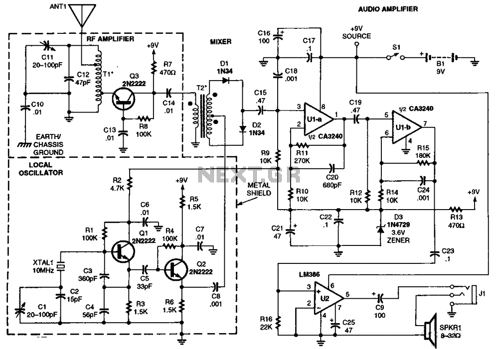
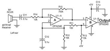
The circuit incorporates an RF amplifier (Q3) that enhances the signal strength before it is processed by the mixer, which consists of diodes D1 to D4. This configuration allows for efficient signal mixing, crucial for applications requiring frequency conversion. The diodes serve as the core mixing elements, where they combine the RF signals with the local oscillator frequency to produce intermediate frequencies.
Transistors Q1 and Q2 are integral to the circuit, acting as switches or amplifiers that control the flow of liquid oxygen, which is injected at a frequency of 10 MHz. The transformers T1 and T2 are used to isolate and match the impedance between the RF amplifier and the mixer, ensuring optimal signal transfer and minimal loss. This injection of liquid oxygen is likely used to enhance the cooling of the RF components, thus improving performance and stability.
Operational amplifiers U1A and U1B are configured to amplify the mixed signals, providing necessary gain before further processing. U2, functioning as an audio amplifier, suggests that the circuit may ultimately be designed for audio applications, converting the mixed signals into audible sounds or further processing them for audio output.
The overall design emphasizes efficient signal processing from RF to audio frequencies, with careful consideration of component interactions and thermal management through liquid oxygen injection. The detailed schematic, referenced in the description, provides visual guidance on the layout and connections between these components, aiding in troubleshooting and optimization of the circuit's performance.RF amplifier Q3 to diode D1-D4 in the mixer, Q1-Q2 through T1 and T2 provide liquid oxygen injection 10MHz for D1, U1A and U1B and U2 is an audio amplifier. Detailed information is shown in the figure T1 and T2.
Related Circuits
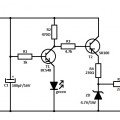
A device designed to locate a mobile phone by emitting intermittent flashes and beeps, indicating the presence of an active mobile phone. This circuit activates even when the mobile phone is in silent mode, making it effective for detecting...
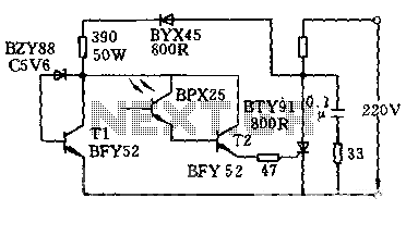
The circuit is designed to activate when the light intensity exceeds 700lx. In this configuration, a phototransistor and the BFY52 transistor are used to trigger the BTY91 thyristor with a current. When light strikes the phototransistor, a positive trigger...
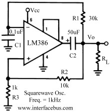
Several operational amplifier circuits are presented here, configured as square wave oscillators. A square wave is a periodic pulse train with a 50 percent duty cycle. The operational amplifier functions as a high-gain amplifier, and oscillation is achieved with...
The following circuit illustrates a 2500W Phase Control Circuit Schematic. Features include a ground-tied trigger output that is disabled, and a low voltage input. The 2500W Phase Control Circuit is designed to regulate the power delivered to a load by...
Assistance is required regarding the circuits provided below. The focus is on an ultrasonic receiver circuit that utilizes two ultrasonic components. The ultrasonic receiver circuit is designed to detect ultrasonic waves, typically in the frequency range of 20 kHz to...
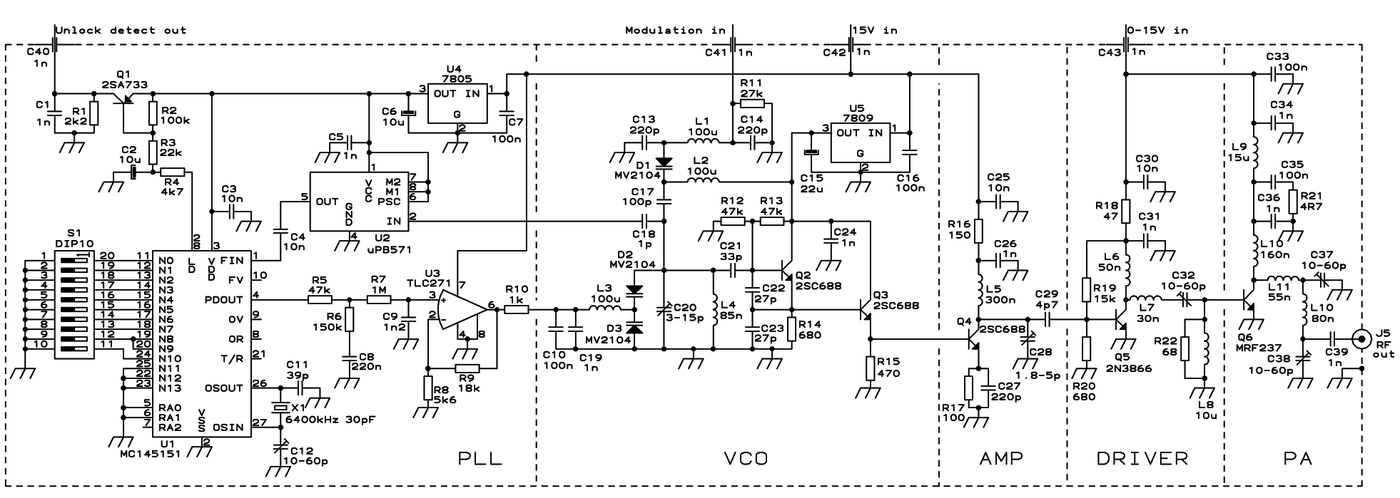
The PLL transmitter exciter is designed to provide a stable, low noise, frequency-selectable RF signal, which is amplified to a controllable output power sufficient to drive a power amplifier. It utilizes a PLL frequency synthesizer based on the MC145151,...
Warning: include(partials/cookie-banner.php): Failed to open stream: Permission denied in /var/www/html/nextgr/view-circuit.php on line 713
Warning: include(): Failed opening 'partials/cookie-banner.php' for inclusion (include_path='.:/usr/share/php') in /var/www/html/nextgr/view-circuit.php on line 713