
Medical treat ventilator controller
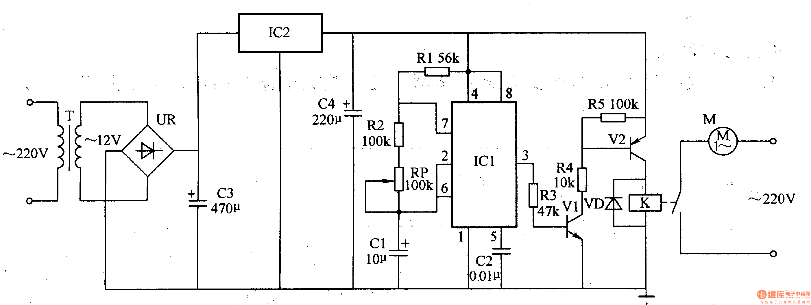
The medical ventilator controller circuit is designed to regulate the operation of a ventilator, ensuring that patients receive the appropriate airflow and pressure during mechanical ventilation. The astable oscillator serves as a timing source, generating a continuous square wave signal that controls the breathing cycle of the ventilator. The configuration of the oscillator is defined by the values of resistors R1, R2, the potentiometer RP, and capacitors C1 and C2, which set the frequency and duty cycle of the output waveform.
The time base integrated circuit IC1 is fundamental in establishing the oscillator's timing characteristics, allowing for precise control over the ventilatory patterns. The output from the astable oscillator is fed into the control circuit, which is responsible for interpreting the timing signals and managing the operation of the ventilator's actuators.
The control circuit utilizes resistors R3 to R5 to set the gain and biasing of the transistors V1 and V..., which act as switches or amplifiers to control the power delivered to the ventilator's drive mechanisms. This configuration ensures that the ventilator can respond dynamically to changes in patient demand, providing adequate support during inhalation and exhalation phases.
Additionally, the power supply circuit is crucial for maintaining the necessary voltage levels for the entire system, ensuring reliable operation of the oscillator and control circuits. This circuit may include voltage regulators and filtering components to provide stable and clean power to the various elements of the ventilator controller.
Overall, the integration of these components within the medical ventilator controller circuit allows for effective and responsive ventilation therapy, critical for patients requiring assisted breathing. The design emphasizes reliability and precision, essential characteristics for medical devices operating in critical care environments.The medical treat ventilator controller circuit is composed of astable oscillator, control circuit and power supply circuit, it is shown in the figure 9-155. The astable oscillator circuit is made of resistors R1, R2, potentiometer RP, capacitors C1, C2 and time base integrated circuit IC1.
The control circuit consists of resistors R3-R5, transistors V1, V.. 🔗 External reference
Related Circuits
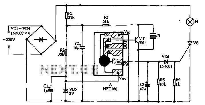
220V AC power is supplied through a VD1 to VD4 bridge rectifier and a voltage regulator circuit involving R1, R2, and VD5 components. The output provides a DC voltage of approximately 3V, which powers the manifold A. The manifold...
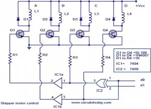
The following circuit illustrates a Stepper Motor Controller Circuit Diagram. This circuit is based on the 7404 IC. Features include a simple stepper motor. The stepper motor controller circuit utilizing the 7404 IC is designed to drive a stepper motor...
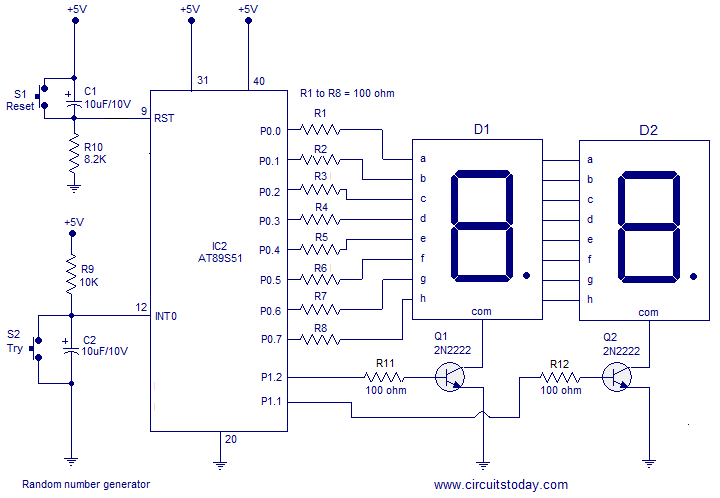
A simple random number generator utilizing the 8051 microcontroller. The AT89S51 is the controller employed in this setup. The circuit design for the random number generator based on the AT89S51 microcontroller involves several essential components and connections. The AT89S51 microcontroller,...
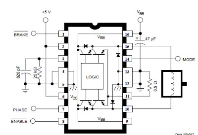
The A3952S integrated circuit, designed by Allegro MicroSystems, can be utilized to create straightforward and effective motor driver circuits. A previous article discussed a basic bipolar stepper motor driver circuit that employs two A3952S circuits. The A3952S is capable...
National Instruments Multisim now features microcontroller unit co-simulation capabilities, enabling the inclusion of a microcontroller, programmed in assembly or C code, within SPICE-modeled circuits. The MCU functionality in Multisim allows students, educators, and professional users to program MCUs in...
At half brightness, the lamp current is pulsed on and off by the voltage developed across the resistor and capacitor at the current-sense output. The current-sense output detects the lamp current. A basic pulse-width modulation (PWM) lamp-brightness control circuit...