
Mesa Mark IIc+ Preamplifier

The Mark IIc+ amplifier's design emphasizes simplicity and functionality while maintaining the characteristics that made the original model famous. The stripped-down version focuses on the lead channel, providing a straightforward user experience without the complexities of switching features. The decision to replace the last preamp stage with an AC-coupled cathode follower enhances the amplifier's versatility, allowing it to drive various effects and accommodate long cable runs without compromising the sound quality.
The use of poly film capacitors throughout the circuit, both for cathode bypass and coupling, contributes to a clean signal path, minimizing unwanted distortion and noise. The choice of resistors, primarily metal film types, ensures stability and accuracy in the circuit's performance, further enhancing the amplifier's overall sound quality. The custom toroidal transformer is designed to meet specific performance criteria, ensuring efficient power delivery and low noise operation.
The careful attention to grounding and layout design minimizes interference and enhances the reliability of the amplifier. By implementing a strict ground bus scheme, the amplifier maintains a clean and organized signal path, reducing the likelihood of ground loops and associated noise issues. The use of shielded wire for critical signal paths further protects against electromagnetic interference, ensuring optimal performance in various playing environments.
Overall, the construction of this Mark IIc+ variant reflects a deep understanding of amplifier design principles, prioritizing sound quality, user customization, and reliability in a compact form factor.Mark IIc+ has a reputation of being one of the most sought after amps today. Only 1500 of them were made back in the 80 ²s and these days they go for up to 4000-5000$ a piece. One of the players that made this amp famous is John Petrucci. Being a Petrucci fan I couldn`t resist building it, since I can`t afford to actually buy one I decided to bui ld a stripped-down version featuring lead channel only without fancy switching. Bass shift and lead bright switches are left in but as board mounted DIP switches. That way I can play with them to find the position I like and leave it like that. The last preamp stage on the original IIc+ doesn`t do much as far as overdrive characteristics are concerned. It shapes bass response of the output stage which I don`t have. Voltage divider between 5th and 6th stage reduces signal level to just few volts to make it effect friendly.
Since I`m building the preamp only I don`t need the last stage to boost the signal back. Instead, I converted the last stage to AC coupled cathode follower. It`s supposed to be a transparent buffer that will provide nice low impedance output that should drive any effect and long cables if needed. Since it doesn`t cut any bass, it will essentially have similar response like the original stage with deep pulled out.
If you want to learn more about AC cathode followers, Merlin has a great article posted here. Large 15uF cathode bypass caps are replaced with 6. 8uF poly caps. These were the largest I had and there`s no much noticeable difference in bass response between 6. 8uF and 15uF. Heaters are run at 12. 6V to reduce radiation less current means less radiation and therefore less chance of noise. Also, they are elevated to ~80V using a 220K:47K voltage divider right after the first filter cap. Click here to view hand-drawn layout I used to build the board. Note that it doesn`t include DIP switches and doesn`t show series resistors I ended up using for values I didn`t have. Cathodes, grids and plates are marked Cx, Gx and Px respectively, where x is tube index. T, M, B, etc markings on the bottom side are pot connections; e. g. T stands for Treble. There are no electrolytic capacitors anywhere in the preamp! Power supply uses (giant) motor run (not motor start) poly film capacitors. As mentioned before, cathode bypass caps are also poly film. Coupling caps are mostly Russian PIO with a couple of poly film. Small capacitors in the pF range are mix of ceramic and silver mica type. Mica are notorious for being harsh when used as treble bypass/coupling caps so I used them only to shunt higher frequencies to ground.
Resistors are mostly Dale and Xicon. 2W metail film resistors were used for plate resistors wherever I had that value. Transformer is a custom wound toroidal built to these specs: I used the same chassis like for Soldano Preamp, just a bit shorter and powder coated in cream. It`s a great chassis to work with because each panel may be removed separately. I wired the pots with the front panel removed. Tube sockets are wired before installing it back to allow easier access. Shielded wire is used on the input, from volume pot to the socket and to/from lead drive pot. For circuit board I used two fiberglass perfboards joined together. Doesn`t look as fancy as a nice eyelet board but gets the job done. As you can see below, chassis is packed tightly. Motor run caps are huge and don`t leave too much free space. A couple of times I used two resistors and capacitor to get the right value simply because I didn`t have it As far as grounding is concerned, (almost) strict ground bus scheme is used.
Thick bare copper wire is used as a bus and is grounded to the chassis very close to the input jack. Components are grounded to the bus in the same way they appear in the signal flow. This also applies to the filter caps. First cap is grounded at the end of the bus and the rest of them are grounded close to the tubes t 🔗 External reference
Related Circuits
When the start switch is pushed, the output of the charger goes to 14.5 V. As the battery approaches full charge, the charging current decreases and the output voltage is reduced from 14.5V to about 12.5V, terminating the charging...
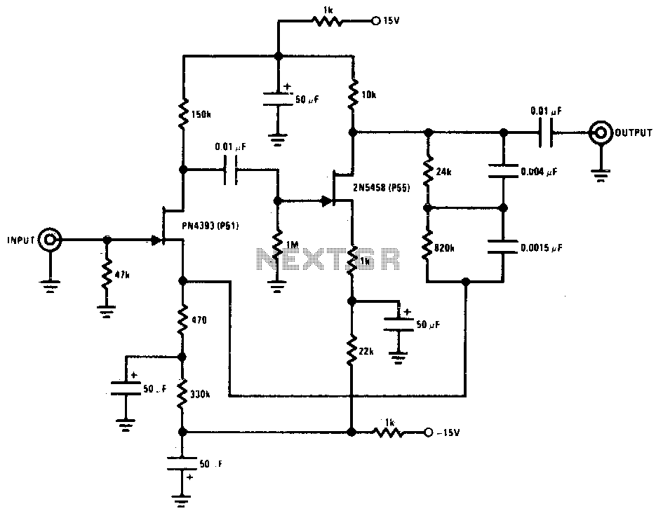
This preamplifier offers a loading ratio of better than -70 dB (referenced to a 10-ohm reluctance phono cartridge) and accepts millivolt input at 1 kHz. It has a dynamic range of approximately 35 dB of gain at 1 kHz...
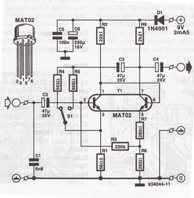
The microphone preamplifier circuit design presented in this schematic utilizes the SSM2015 component manufactured by Precision Monolithics Inc. (PMI). This component provides high amplification with low noise characteristics (1.3nV/f). The design is configured to handle differential input signals and...
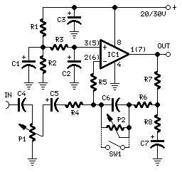
This preamplifier was designed to cope with CD players, tuners, tape recorders etc., providing a gain of 4, in order to drive less sensitive power amplifiers. As modern Hi-Fi home equipment is frequently fitted with small loudspeaker cabinets, the...
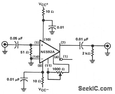
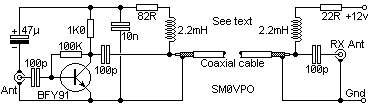
The circuit provides a voltage gain of 20 ±0.1 dB within a frequency range of 500 kHz to 50 MHz. The low-frequency response of the amplifier can be enhanced by increasing the value of the 0.05 µF capacitor connected...
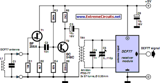
A popular project among microcontroller enthusiasts is to build a radio-controlled clock. Tiny receiver boards are available, equipped with a pre-adjusted ferrite antenna, which receive and demodulate the DCF77 time signal broadcast from Mainflingen in Germany. The DCF77 signal...