
VHF preamplifier with BFY91
If the DC power is switched OFF the preamplifier will become inactive and the relay will bypass the amplifier. In this manner, it may be used with a low-power transmitter (typically up to 10 watts). My first switch was built inside the balun housing of a 2-metre beam antenna.
Note that the DC 12 volts should NEVER be applied whilst transmitting or the poor little BFY91 will be blown to bits. There is also a short delay between removing the DC and the preamp dropping out into a safe condition for transmitting. I should have used a pair of back-to-back diodes across the input to the preamp (before the 100p) to protect the preamp, but I got away with it for a couple of years without a problem.
The circuit operates with a start switch that, when activated, initiates the charging process, resulting in an output voltage of 14.5 V. As the battery nears full charge, the charging current diminishes, and the output voltage decreases to approximately 12.5 V, signaling the end of the charging cycle. Transistor Q1 is employed to illuminate an LED, providing a visual cue that the battery is fully charged.
The preamplifier integrated into this design is characterized as a wideband amplifier, capable of delivering a gain of 15 to 20 dB across a frequency range from 1.8 MHz to over 200 MHz. Users may opt to substitute this amplifier with a preferred model tailored to specific frequency bands of interest. The circuit includes 2.2 mH chokes, which must exhibit a minimum reactance of 5000 ohms at the lowest operational frequency. For the frequency of 145 MHz, these chokes can be constructed with a few turns of wire, such as a 10-turn coil with a diameter of 4 mm, paired with a 2.2 mH toroidal inductor.
The relay component of the circuit is specified to have a coil resistance exceeding 1000 ohms and features two-pole changeover contacts. In the implementation, two 5V PCB mounting relays were utilized, each equipped with a single pole changeover contact and a coil resistance of 560 ohms.
In the event that DC power is disconnected, the preamplifier ceases operation, and the relay bypasses the amplifier, enabling compatibility with low-power transmitters up to 10 watts. Caution is advised, as applying 12V DC while transmitting can damage the BFY91 transistor. A delay exists between the removal of DC power and the preamplifier transitioning to a safe operational state for transmission. To enhance protection for the preamplifier, the inclusion of back-to-back diodes across the input prior to the 100p capacitor is recommended, although the circuit has functioned without this modification for an extended period.When the start switch is pushed, the output of the charger goes to 14.5 V. As the batttery approaches full charge, the charging current decreases and the output voltage is reduced form 14.5V to about 12.5V, terminating the charging process. Transistor Q1 then lights the led as a visual indication of a full charge. The actual preamplifier in this circuit is a practical wideband amplfier that gives about 15 - 20dB of gain from 1.8 MHz through to well over 200 MHz.
You will no-doubt replace this circuit for your own favorite amplifier for the band you are interested in. The 2.2mH chokes should have an absolute minimum reactance of 5000 ohms at the lowest frequency to be used.
For 145 MHz these may simply consist of a few turns of wire. I personally used a 10-turn 4mm Dia. coil in series with a 2.2mH torroidal inductor. The relay should have a coil resistance in excess of 1000 ohms and have two-pole changeover contacts. When I built this circuit I used two 5v PCB mounting relays, each having a single pole changeover contact.
The relays each had a 560 ohm coil. If the DC power is switched OFF the preamplifier will become inactive and the relay will pypass the amplifier. In this manner it may be used with a low-power transmitter (typically up to 10 watts). My first switch was built inside the balun housing of a 2-metre beam antenna. Note that the DC 12 volts should NEVER be applied whilst transmitting or the poor little BFY91 will be blown to bits.
There is also a short delay between removing the DC and the preamp dropping out into a safe condition for transmitting. I should have used a pair of back-to-back diodes across the input to the preamp (before the 100p) to protect the preamp, but I got away with it for a couple of years without a problem.
🔗 External reference
Related Circuits
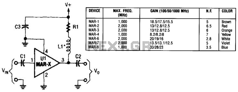
In this basic MAR-x-based circuit, both the input and output consist of a single DC-blocking capacitor (C1 for the input and C2 for the output, respectively). The DC power supply network, which includes L1 and R1, is connected to...
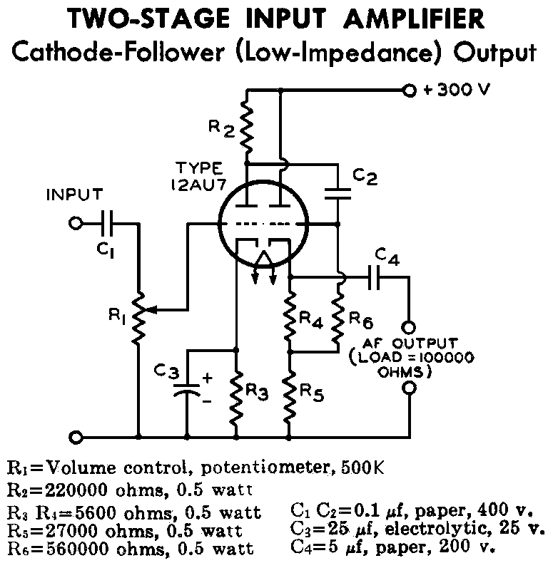
12AU7 (ECC82) Cathode Follower Tube Preamplifier Schematic. This is a two-stage 12AU7 preamplifier featuring a low impedance output stage. The overall gain is approximately 8 times. The 12AU7 (ECC82) tube is a dual triode commonly used in audio applications due...
Radio-frequency schematics (also see NE602 datasheet and application note). This page contains electronic circuits related to RF receivers. This index features a broad collection of RF receiver circuits. Radio-frequency (RF) schematics are essential for designing and implementing circuits that operate...
The circuit was designed to create a modular Class A buffer preamplifier to isolate stages in an audio circuit. BF245 is a general-purpose N-Channel JFET used in this design. The modular Class A buffer preamplifier serves as an essential component...
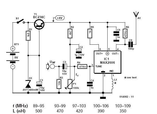
To achieve independence from local radio stations when testing VHF receivers, a frequency-modulated oscillator is required that operates within the range of 89.5 to 108 MHz. However, constructing such an oscillator using discrete components can be quite challenging. Maxim...
This preamplifier is a requirement resulting from many friends to provide a high-quality preamplifier, capable of driving high-quality power amplifiers with good sound. It is not, however, difficult to make; it combines simplicity and handiness. It does not allocate...