
Single-phase motor energy consumption of the two brake circuits

The described circuit utilizes a contactor system to manage the operation of an electric motor during shutdown scenarios. The initial release of contactor KM1 signifies that the system is no longer operational. However, contactor KM2 remains engaged to facilitate the application of a 220V AC power supply. The path through diodes VD1 and VD2 is critical, as these components convert the AC voltage to DC, allowing for effective braking by applying the appropriate current to the motor windings.
The braking process is a crucial safety feature that prevents the motor from coasting to a stop, which could lead to mechanical wear or operational hazards. The use of a time relay (KT) introduces an adjustable delay, allowing for fine-tuning of the braking duration based on the specific requirements of the application. This flexibility ensures that the braking action can be adapted to different load conditions or operational scenarios.
In summary, the circuit's design integrates contactors, diodes, and a time relay to create a reliable braking mechanism for electric motors, enhancing both performance and safety during shutdown procedures. The careful selection of components and their arrangement in the circuit is essential for achieving the desired braking characteristics and operational reliability. Circuit shown in Figure 3-150. When shut down, the contactor KM1 released. KMz pull, 220V AC power supply through the diode VDi, VD2 rectifier, the motor primary and secondary windings with DC current braking, the electric motor into the brake status. After a delay (0. 2-ls, adjustable), time relay KT releases, ending the braking process.
Related Circuits
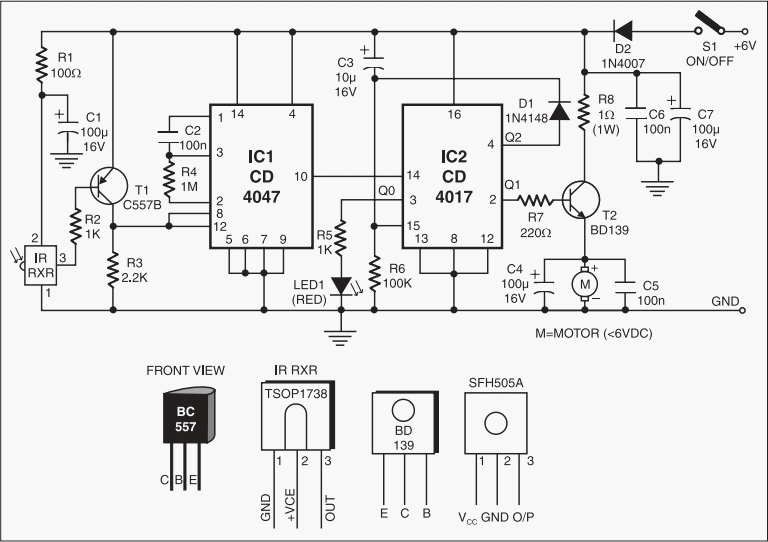
This add-on circuit enables remote switching on/off of battery-operated toy cars using a TV/video remote control handset operating at 3040 kHz. The described circuit utilizes a remote control system to facilitate the wireless operation of battery-powered toy cars. The primary...
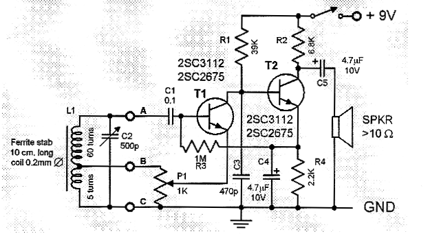
This two-transistor AM radio circuit is also referred to as a "mini-radio." It utilizes only two transistors and a few passive components, which makes it very easy to construct. The two-transistor AM radio circuit operates by utilizing a simple design...
The circuit depicted in Fig. 62-15A is intended to drive a 15-V, two-phase, bipolar stepping motor, delivering a bidirectional single-level voltage across each winding with currents reaching up to 9.6 A. It comprises two identical transistor bridge stages that...
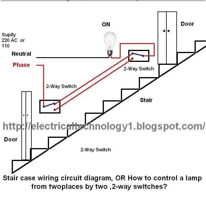
The circuit is complete, and the bulb is ON. To turn OFF the bulb from the upper switch at the top of the stairs, simply turn OFF the switch, which will break the circuit and turn the bulb OFF....
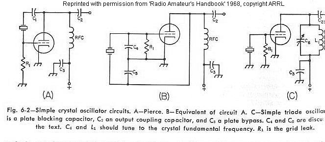
The frequency of a crystal-controlled oscillator is maintained with high precision through the use of a quartz crystal. The frequency is primarily determined by the dimensions of the crystal, particularly its thickness, while other circuit parameters have minimal impact....
This circuit utilizes the principle of capacitance between two plates to detect when multiple sheets of paper are placed between the sensing electrodes simultaneously. CI is the sensing capacitor, composed of two plates measuring 2 inches by 15 inches...