
Metal detector circuit electronic project using transistors

This metal detector circuit employs a straightforward design that integrates essential electronic components to achieve metal detection functionality. The core of the circuit relies on transistors, which act as switches or amplifiers to enhance the detection capabilities. The LED serves as a visual indicator, while a piezoelectric buzzer or speaker can be incorporated to provide an audible alert when metal is present.
The circuit's calibration involves two potentiometers: RV1 and RV2. RV1 is primarily used for initial adjustments to set the detection threshold, while RV2 fine-tunes the sensitivity of the detector. By manipulating RV2, users can optimize the circuit's response to various metal sizes and distances. A faint glow of the LED signifies the detection of smaller or more distant metal objects, while a brighter LED indicates closer or larger objects.
Additionally, the use of a switch (SW1) ensures that the circuit can be activated or deactivated as needed, conserving power when not in use. The overall design is compact and can be easily assembled on a breadboard or PCB, making it suitable for educational purposes or hobbyist projects. Proper attention to component selection and layout will enhance the performance and reliability of the metal detector circuit, allowing for effective metal detection in various environments.This metal detector circuit electronic project is an very simple circuit that is based on common electronic parts. This metal detector circuit electronic project is based on transistors and will provide an visual indication using a LED and an acoustic sound that will inform you when a metal is detected.
You must turn RV2 potentiometer fully cloc kwise and RV2 potentiometer anti-clockwise. With SW1pressed you must turn RV1 anti-clockwise until the LED is about to light and all further sensitivity adjustments should now be done by turning RV2. To set maximum sensitivity, turn RV2 until the LED is weakly lit. The brightness of the Led indicates the distance and the size of the metal object detected. 🔗 External reference
Related Circuits
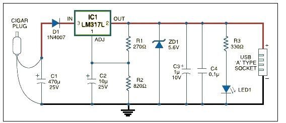
This USB car charger adapter project functions as a DC-DC power converter that effectively converts the 12V car battery voltage into a stable 5V output. It is designed to supply power from a car's cigar lighter socket to any...
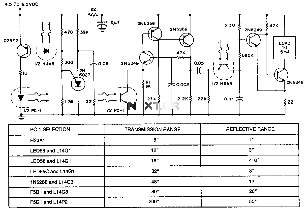
In applications requiring long-range operation with infrared (IR) light sources and high system reliability, pulsed-mode operation of the IR source is essential. Enhanced operational reliability is achieved through synchronous detection of the photodetector current, as implemented in this circuit....
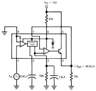
The LM2917 IC chip is specifically designed as a Frequency to Voltage Converter. It requires only a few external components for its operation. The datasheet for the LM2917 IC includes several application examples of the Frequency to Voltage Converter....
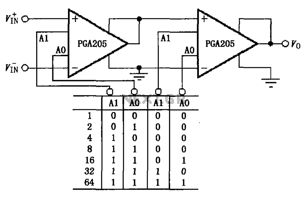
A binary gain step circuit is illustrated using the PGA205, which has a gain range of 1 to 64. The circuit employs two PGA205 devices in cascade, resulting in a total gain that is the product of the individual...
Coin detector and counter: How to detect different types of coins from their effect on an oscillating magnetic field. A coin detector and counter operates by utilizing the principles of electromagnetic induction to identify and differentiate between various types of...
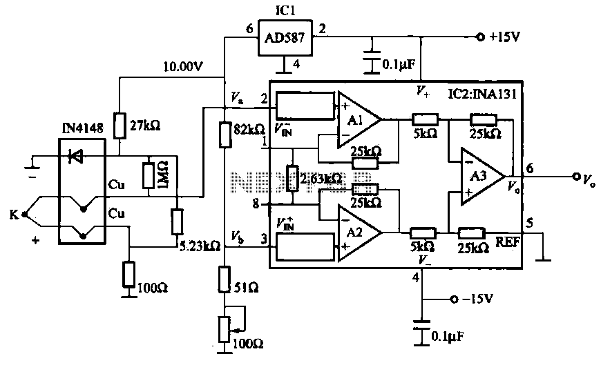
The AD587 is a precision voltage reference providing a 10 V output, generated using a 27 kΩ resistor along with a compensation diode (1N4148) and a thermocouple. This setup connects to the VI + N terminal of a differential...
Warning: include(partials/cookie-banner.php): Failed to open stream: Permission denied in /var/www/html/nextgr/view-circuit.php on line 713
Warning: include(): Failed opening 'partials/cookie-banner.php' for inclusion (include_path='.:/usr/share/php') in /var/www/html/nextgr/view-circuit.php on line 713