
coin detector and counter
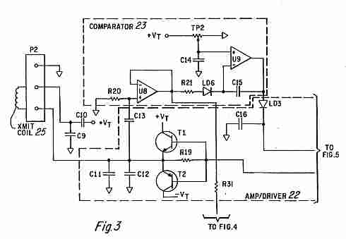
A coin detector and counter operates by utilizing the principles of electromagnetic induction to identify and differentiate between various types of coins. The system typically consists of an oscillating magnetic field generated by an inductor or coil. When a coin enters the field, it alters the magnetic flux due to its conductive properties. This change in the magnetic field induces a current in the coin, which in turn generates its own magnetic field.
The circuit design usually includes a high-frequency oscillator to produce the oscillating magnetic field. The frequency of oscillation is chosen based on the expected properties of the coins to be detected, as different metals will interact with the magnetic field differently. The induced currents in the coins will produce varying impedance, which can be measured by a microcontroller or an analog circuit.
The detection mechanism may involve a comparator circuit that compares the impedance changes against preset thresholds corresponding to different coin types. This allows the system to distinguish between coins made of different materials, such as copper, nickel, and zinc, based on their unique electromagnetic signatures.
Furthermore, the output from the detection circuit can be interfaced with a digital counter to tally the number of coins detected. This counter can be designed to display the total value of the coins based on their types and quantities, providing a comprehensive solution for coin detection and counting in various applications, including vending machines and coin sorting systems.
In conclusion, a coin detector and counter leveraging an oscillating magnetic field is an effective electronic solution for identifying and quantifying different coin types through their electromagnetic interactions.Coin detector and counter : How to detect different types of coins from their effect on an oscillating magnetic field.. 🔗 External reference
Related Circuits
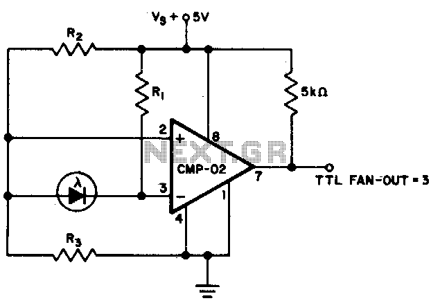
The output state changes at a photodiode current of 0 µA. For R1 = 2 MΩ, R2 = R3 = 5 MΩ. The described circuit likely involves a photodiode used in conjunction with resistors R1, R2, and R3 to create...
The core component of this DIY metal detector circuit is the CS209A integrated circuit (IC). The metal detector is constructed using a single 100µH coil, which has a diameter of 40 mm. The CS209A IC serves as the primary signal...
Dynamic flip-flops ignore pulses at their inputs that are shorter than 40 ns or do not have TTL levels. This limitation renders TTL flip-flops inadequate for capturing noise pulses with unknown durations and amplitudes. This issue is familiar to...
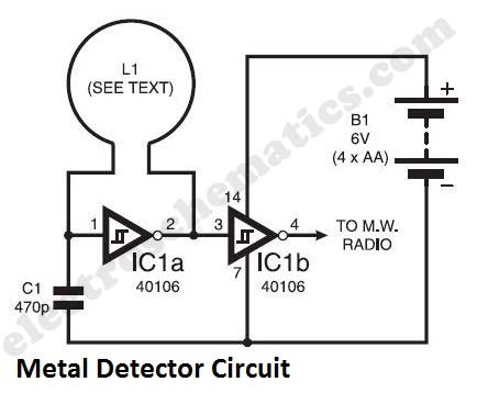
The metal detector circuit presented here exemplifies simplicity while demonstrating effective functionality. It utilizes a single 40106 hex Schmitt inverter IC, a capacitor, a search coil, and batteries. A connection from IC1b pin 4 must be made to a...
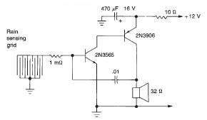
This rain detector electronic circuit project is a simple alarm circuit that activates an audio warning when liquid is detected on the sense pad. The circuit diagram is based on two transistors. When the sense pad conducts, transistors Tr1...
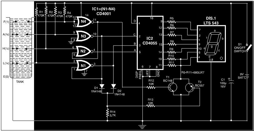
This circuit is a fluid level indicator that displays each level using meaningful English letters. It employs a seven-segment display to represent the letters E for empty, L for low, H for half, A for above average, and F...