
model train detector using photocell

The described photocell circuit is designed for applications where light detection is necessary, such as in model railroading or outdoor lighting systems. It is essential to mount the photocell at tie level between the rails to ensure optimal light exposure for accurate readings.
The circuit utilizes a variable resistor, commonly known as a potentiometer, which allows for the adjustment of sensitivity. This feature is crucial as it enables the user to calibrate the photocell to respond to varying levels of ambient light, accommodating different environmental conditions or specific user requirements.
Powering the circuit can be achieved with either 6 volts or 12 volts, providing flexibility based on the relay specifications used in conjunction with the photocell. When selecting a relay, it is critical to ensure compatibility with the operating voltage. Some relays are rated for 5 volts; however, they can typically handle 6 volts without issues. It is advisable to verify the relay's specifications to prevent any potential damage or malfunction.
The circuit layout should include a photocell sensor, the variable resistor, and a relay connected to an appropriate load. If the circuit is to be used in an outdoor environment, it should be housed in a weatherproof enclosure to protect the components from moisture and dust. Proper wiring practices should be followed to ensure reliable operation, including secure connections and insulation of exposed wires.
In summary, this photocell circuit with adjustable sensitivity and dual voltage options is suitable for various applications, provided that the proper relay is selected and installed correctly.This photocell is best mounted at tie level between the rails. The variable resistor adjusts the sensitivity of the circuit. This circuit can be powered by either 6 or 12 volts - BE SURE to use the proper relay; note that some relays are rated for 5 volts, these should be okay with 6 volts. 🔗 External reference
Related Circuits
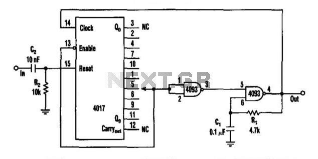
This circuit features a rate multiplier utilizing a 4093 Schmitt trigger configured as an oscillator, which drives a 4017 decade counter. When a pulse is present at the input (to C2), the 4017 is reset, causing output zero to...
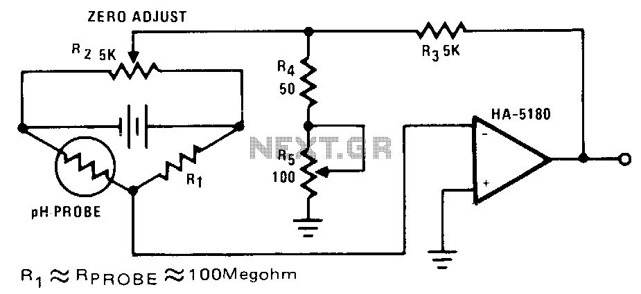
The highest sensitivity is attained when R1 is roughly equal to the probe resistance. The circuit can be calibrated to zero using R2, while R5 regulates the full-scale voltage. The relationship between pH and output voltage may not be...
Audio Amplifier with output power of either 100W or 130W. The output configuration can accommodate 2 transistors for 90W output or 4 transistors for 130W output. The PCB layout utilizes T3 on the heatsink. The component reference and values...
This is a coincidence detector circuit. This circuit is very useful for monitoring complex logic circuits. This circuit has two inputs, A and B. If A and B are... The coincidence detector circuit is designed to identify when two input...

An audio power amplifier circuit for a 3-watt stereo amplifier using the MAX 7910 IC is explained below. The audio power amplifier circuit utilizing the MAX 7910 IC is designed to deliver a maximum output power of 3 watts per...
This circuit detects the presence of objects through the reflection of infrared light, providing a direct digital output for object detection. By utilizing modulation and high-power bursts of infrared light at a very low duty cycle, it achieves a...