
USB Interface Board Tutorial Using PIC18F4550
The USB Interface Project utilizing the PIC18F4550 microcontroller is designed to create a bridge between a computer and various electronic devices, enabling control through USB connectivity. The project employs the PIC18F4550 due to its capabilities as an HID, allowing for seamless integration with modern operating systems without requiring extensive driver installations.
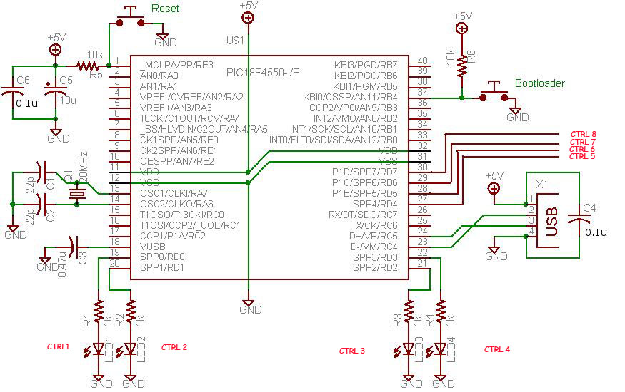
The circuit design typically includes the PIC18F4550 microcontroller, which is connected to a USB port for communication with the computer. The microcontroller is programmed to interpret commands from the C# application and control outputs, such as LEDs or motors, accordingly. The USB board is designed to include necessary components such as capacitors, resistors, and possibly a voltage regulator to ensure stable operation.
The schematic for this project would include the following key components:
1. **PIC18F4550 Microcontroller**: The core of the project, responsible for processing inputs and controlling outputs.
2. **USB Connector**: A USB Type-A or Type-B connector for interfacing with the computer.
3. **LEDs**: Configured to indicate status or provide visual feedback based on the control signals from the microcontroller.
4. **Resistors**: Used in series with LEDs to limit current and prevent damage.
5. **Power Supply Circuit**: To provide the necessary voltage levels for the microcontroller and connected devices.
6. **Decoupling Capacitors**: Placed near the power pins of the microcontroller to filter out noise and ensure stable operation.
The software component involves writing a C# application that sends commands to the microcontroller via the USB connection. This application can include a graphical user interface (GUI) with buttons to control the connected devices. The interaction between the software and hardware is facilitated by the HID capabilities of the PIC18F4550, allowing for straightforward command transmission.
In summary, the USB Interface Project using the PIC18F4550 microcontroller serves as an educational platform for understanding USB communications and microcontroller interfacing, suitable for both beginners and experienced users. The detailed construction process, from circuit design to software implementation, provides a comprehensive learning experience in electronics and programming.This project demonstrates a computer control interface using a USB Board. (USB INTERFACE PROJECT). This tutorial will show you a simple way to control some device like led, motors and other devices with computer through a USB Board. The traditional way to control devices from a computer was to use a parallel printer port which is much more easy to
implement than that of a USB PROJECT, but the only limitation with parallel printer port is that the latest computer does not comes with parallel printer port. So you can use this project as an alternative to a parallel port interface. pic18f4550 usb interface project is Human Interface Device (HID). This tutorial is not so difficult for a experienced person however I am also posting a step by step procedure for beginners.
If you are an experienced person with microcontroller then all you need to do is to make the USB board Circuit and then burn the firmware into the microcontroller, with a microcontroller programmer and then install the drivers on your system, and finally launch the application after connecting the main board to the computer with a USB PORT. -Experienced personal can go to end of Interface Board link and can download everything at the end of that page.
Beginners can follow this page and continue on for full description. - This project allows you to control some device with your computer on clicks of few buttons on a small application written in C# which communicates through the pic18f4550 microcontroller. But creating this board can be difficult for beginners and easy for experienced persons. In traditional parallel printer port interface project all you have to do is to connect few led`s across you parallel port (printer port) and code an application in Visual Basic or C# and you are done.
But when it comes to USB port control, its quiet complex way than parallel printer port control. This Tutorial will show you in details for constructing this USB pic18f4550 circuit and running it from a C# application. Please read and follow all the posts. I found a kind of tutorial on microchip. com to control one led with PIC18F4550, and from there I started to do experiments on source codes and then I came up with controlling 8 led`s.
For now I am showing only 6 LED controls. This USB Interface board pic18f4550 is programmed to control 6 led`s and it can be manipulated easily to control 8 led`s. In spite of led`s you can interface it to some other electronics components to control, like DC motor or stepper motor or can make your own robotics application as I did.
A small software coded in C# can control the glowing of led`s with clicks of mouse or by pressing some keys. Let`s start with making the circuit board first, then we will discuss about other coming steps for making this demo interface development board like firmware, Driver, bootloading, writing our own code using MPLAB IDE, etc.
Please read all my steps carefully and follow them properly, in first reading it may not be so much clear, so I suggest giving a second reading. As you go further, it will start to get clear slowly. I am trying to make it as easy as possible for better understanding. It is recommended to use a PCB for making this USB Interface Board. Over breadboard there are always chances of loose connections. On a Breadboard Sometime all the connections are perfect but still the PIC18F4550 is not detected by the system, (it will freak you out), so better way is to use a PCB, I myself faced this problem, even though all the circuitry and connections were perfect and all checked up several times, but still no sign of life.
So better to use a PCB on the first shot. You can alter the connection anytime on PCB if any mistake is detected on the USB interface board you are making. -There are some basic things that you must always be cautious about while experimenting with any microcontroller.
One thing that you must always be cautious about is, the v 🔗 External reference
Related Circuits
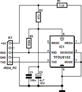
Many modern motherboards are equipped with an infrared data interface compliant with the IrDA standard, but this interface is not very often used. However, it is straightforward to build a data transmission module and connect it to the corresponding...
There are many who built the Easy Programmer or C-52 Evaluation Board, asking for the RS232C level converter chip, DS275. Many have changed to MAX232 instead, because it is not available in their home. Here is another simple and...
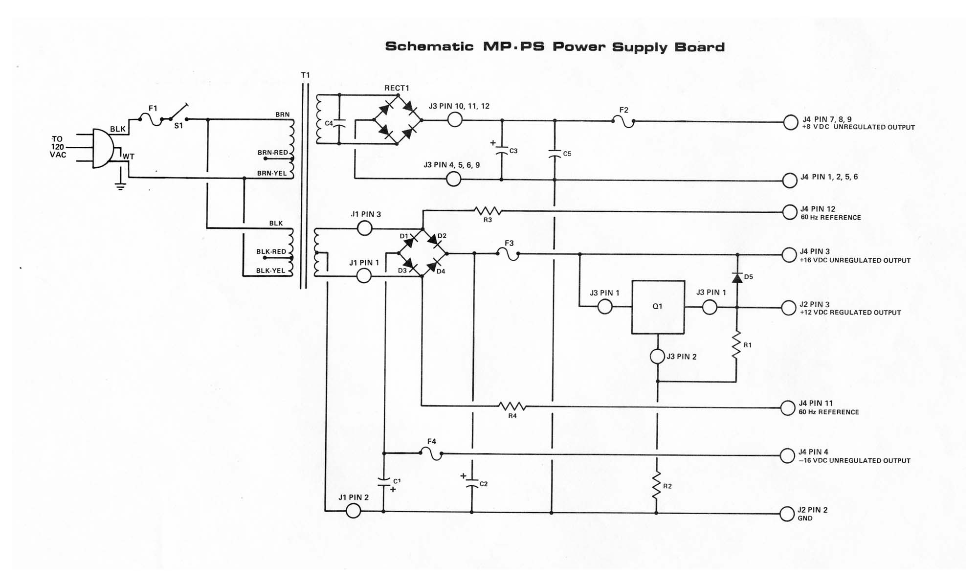
The MP-P2 Power Supply is engineered to provide power to the motherboard and its associated plug-on boards, including the MP-09 Microprocessor Board, disk controller board, memory boards, and up to eight interface boards within the SWTPC Computer system. It...
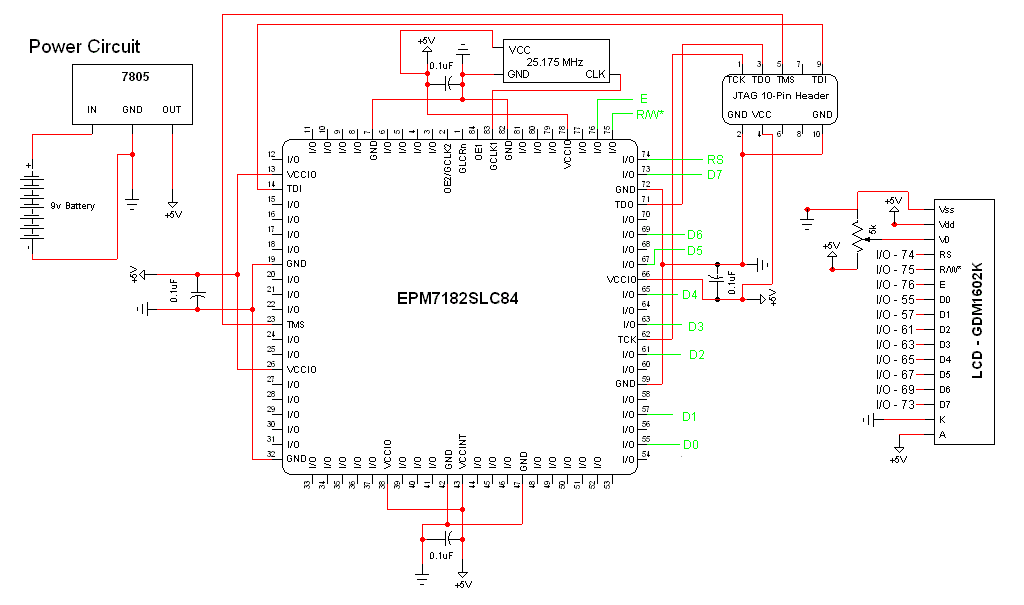
The schematic for this project is a modified version of the CPLD development board schematic. Several new components have been added for this project, and the completed schematic is presented below. The primary components in the schematic include the...

Voltage regulator ICs (78xx series) provide a steady output voltage, in contrast to a widely fluctuating input supply, when the common terminal is grounded. The 78xx series of voltage regulator integrated circuits (ICs) are widely utilized in electronic circuits to...
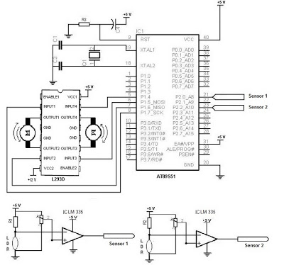
The electronic schematic of the Light Detector Robot can be divided into three main components: the sensor, the microcontroller, and the DC motor driver. The light sensor utilized in this design is a Light Dependent Resistor (LDR), which alters...