
Metal detector with 4030 CMOS
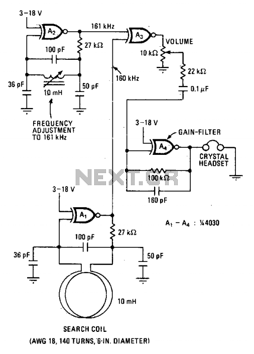
This metal detector circuit is designed to operate efficiently on battery power, making it portable and convenient for field use. The heart of the circuit lies in the 4030 CMOS integrated circuit, which houses four exclusive-OR gates. These gates are pivotal in establishing two oscillators, where gates A1 and A2 are configured to oscillate at closely spaced frequencies of 160 kHz and 161 kHz. This slight frequency difference is crucial for the detection mechanism, as it allows for the generation of beat frequencies when the oscillators interact.
The search coil, positioned in proximity to the target metal, serves as an inductive element that influences the oscillator's frequency. The presence of metal alters the inductance of the coil, thereby changing the oscillation frequency. This change is detected by the mixing stage, represented by gate A3, which combines the outputs of the two oscillators. The mixing process results in two primary output frequencies: a low frequency of 1 kHz and a higher frequency of 321 kHz.
To isolate the desired signal, a low-pass filter (A4) is employed, which effectively attenuates the 321 kHz frequency while allowing the 1 kHz signal to pass through. This filtered 1 kHz signal is then amplified to drive a crystal headset, providing audible feedback to the user. The design ensures that the metal detector is sensitive enough to identify coin-sized objects located up to one foot away, making it suitable for various treasure-hunting applications. The use of CMOS technology ensures low power consumption, extending battery life and enhancing the usability of the device in outdoor environments.This battery-powered metal detector uses four exclusive-OR gates contained in the 4030 CMOS integrated circuit. The gates are wired as a twin-oscillators and a search coil serves as the inductance element in one of the oscillators.
When the coil is brought near metal, the resultant change in its effective inductance changes the oscillator's frequency. Gates A1 and A2 form the two oscillators which are tuned to 160 and 161 kilohertz respectively. The pulses produced by each oscillator are mixed in A3, its output contains sum and difference frequencies at 1 and 321 kHz. The 321 kHz signal is filtered out by the 10 kHz low-pass filter at A4, leaving the 1 kHz signal to be amplified for the crystal headset connected at the output.
The device's sensitivity is sufficient to detect coin- sized objects a foot away. 🔗 External reference
Related Circuits
A peak detector is a circuit that detects the peak voltage of an incoming waveform. It is primarily used as an Amplitude Modulation (AM) detector, Pulse Amplitude Modulation (PAM) detector, or envelope detector. The basic form of a peak...
The NAND gates utilize a CMOS 4011 chip, which is a low-power component ideal for battery-operated circuits. This chip is powered by a 5V voltage supplied from an LM7805L regulator. The purpose of this regulation is to maintain a...
Portable loads such as video cameras, halogen flood lights, electrical irons, hand drills, grinders, and cutters are powered by connecting long 2- or 3-core cables to the mains plug. Due to prolonged usage, the power cord wires are subjected...
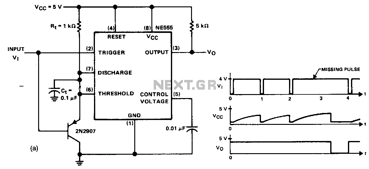
This circuit detects a missing pulse or an abnormally long interval between consecutive pulses in a pulse train. The timer is configured in monostable mode, with the time delay set slightly longer than the duration of the input pulses....
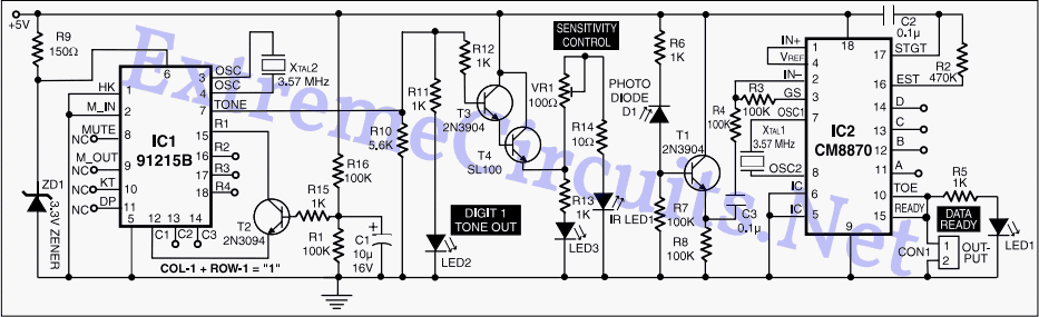
A DTMF-based infrared (IR) transmitter and receiver pair can be utilized to create a proximity detector. This circuit enables the detection of any object capable of reflecting the IR beam and moving in front of the IR LED and...
Cellular phone detector circuit schematic using common electronic parts The cellular phone detector circuit is designed to identify the presence of a cellular phone within a specified range. This circuit utilizes basic electronic components, making it accessible for hobbyists and...