
555 timer Pulse generator

The Pulse Generator kit utilizes the LM555 timer integrated circuit, a versatile and widely used component in timing applications. This particular kit is designed to generate pulse signals in the frequency range of 1 Hz to 180 KHz, making it suitable for a variety of testing and experimentation purposes. The frequency output can be easily adjusted using jumper settings, allowing users to select from predefined ranges or tune it to specific values as needed.
The power supply requirement for the kit is a maximum of 12 VDC with a current draw of 40 mA, ensuring compatibility with standard power sources. The inclusion of a Power-On LED indicator provides a visual confirmation that the circuit is powered and operational, enhancing usability during testing and development.
For ease of integration into various projects, the kit features terminal pins that facilitate straightforward connections to other components or test equipment. Additionally, the PCB is equipped with four mounting holes, each measuring 3.2 mm, allowing for secure installation in enclosures or on breadboards.
The compact dimensions of the printed circuit board (PCB) at 40 mm x 47 mm make it suitable for use in space-constrained applications. Overall, the Pulse Generator kit represents a practical solution for engineers and hobbyists looking to create reliable pulse signals for testing and experimentation in electronic projects.Pulse Generator kit will generate a frequency in KHz which can form a good test gear project. This kit is based on the classic LM555 timer IC. Input - 12 VDC Max @ 40 mA. Range - jumper selectable and preset tunable range of 1 Hz to 180 KHz. Power-On LED indicator. Terminal pins for easy connection. Four mounting holes of 3.2 mm each. PCB dimensions 40 mm x 47 mm 🔗 External reference
Related Circuits
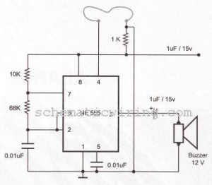
The circuit of a burglar alarm utilizing IC timer 555/556 functions as a security measure to prevent unauthorized entry into a premises. The alarm generates a loud sound when a thin wire connecting resistor R1 with pin 4 of...

Press SI. The 100 µF electrolytic capacitor rapidly charges up from approximately 0 V. The transistor becomes forward biased, allowing collector current to flow and operate the relay. When SI is released, the capacitor discharges through the 33 K...
Do not use the on-board relay to switch mains voltage. The board's layout does not provide adequate isolation between the relay contacts and the low-voltage components. If mains voltage switching is required, mount a suitably rated relay in a...
This application report presents a potential solution to the telecom plug-in power issue, utilizing a nominal 48 Vdc system bus and a module that requires two low-voltage supply outputs. It includes a comprehensive design methodology for customizing the circuit...
This circuit is intended to let the user turn off a lamp by means of a switch placed far from bed, allowing him enough time to lie down before the lamp really switches off. 15 seconds delayed switch-off. A...
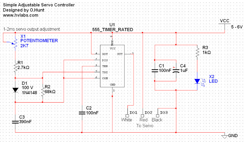
Servos are valuable components for various applications, including robotics, automation, and remote control tasks, such as steering model vehicles. They are relatively inexpensive and readily available; however, controlling them can be somewhat challenging as they require specific timing to...