
Simple timer
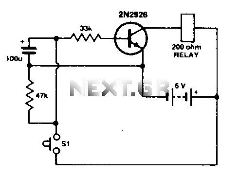
The described circuit utilizes a 100 µF electrolytic capacitor, a transistor, and a relay to create a time delay mechanism. Initially, when switch SI is pressed, the capacitor charges quickly from a low voltage, which forward biases the transistor. This condition allows current to flow from the collector to the emitter, activating the relay. The relay remains engaged as long as the transistor is conducting.
Upon releasing switch SI, the capacitor begins to discharge through a 33 K ohm resistor connected to the base of the transistor. The discharge of the capacitor is a critical aspect of the timing function in this circuit. As the voltage decreases, it eventually reaches a threshold (approximately 0.5 V) where the transistor no longer receives sufficient base current to remain in the forward-biased state. Consequently, the collector current stops, and the relay is deactivated.
The additional resistor of 47 K ohms provides a path for the capacitor to continue discharging, ensuring that the time delay is effectively managed. The specified configuration allows the relay to remain activated for approximately eight seconds, which can be adjusted by modifying the capacitance or the resistance values.
For applications requiring longer activation times, the circuit can be enhanced by replacing the standard transistor (2N2926) with a Darlington pair configuration. This substitution increases the current gain, allowing for the use of lower capacitance values while still achieving the desired relay activation duration. In such cases, it is advisable to increase the resistance values to the megohm range to maintain the desired discharge time constant and ensure stable operation of the circuit. This design is particularly useful in applications where a timed relay activation is necessary, such as in automation systems or timing circuits.Press SI. The 100 µF electrolytic capacitor rapidly charges up at about 0 V. The transistor will be forward biased, and collector current will flow operating the relay. Release SI. The capacitor will begin to discharge via the 33 K resistor at the base of the transistor. When the voltage across the capacitor gets down to half a volt or so, the transistor base will no longer be forward biased, collector current will cease, and the relay will drop out. The capacitor will continue to discharge via the 47 K resistor With the values shown, the relay will remain operated for about eight seconds. Long times are possible with lower values of capacitance by substituting a Darlington pair for the 2N2926. In this case, increase the two resitor values into the megohm range. 🔗 External reference
Related Circuits
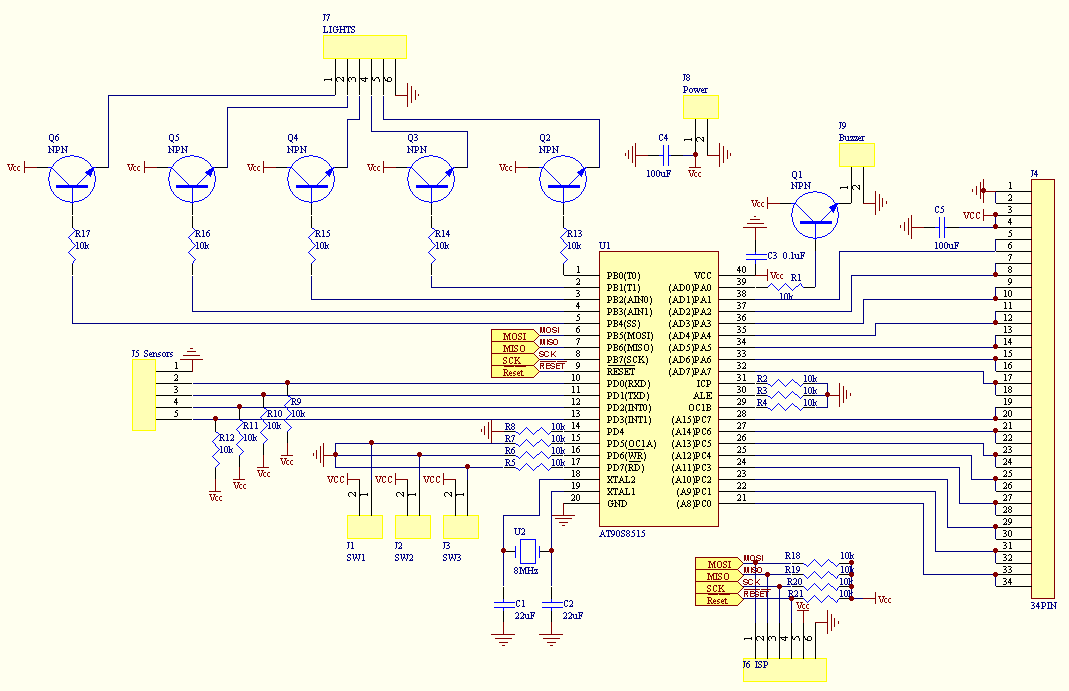
TrackTimer1 was a straightforward project involving basic electronics for car detection, a simple Parallel Port interface to the PC, and software for an F1-style display. The motivation for TrackTimer2 was to create a lap counter suitable for outdoor use,...
this is a very easy circuit to build - all parts can be found at the local electronics shop. The described circuit is characterized by its simplicity and accessibility, making it an ideal project for beginners or those looking to...
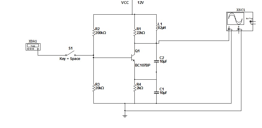
To simulate this circuit, NI Multisim produced by National Instruments is required. The oscillator will generate a stable waveform. If a file needs to be saved, navigate to the source code. It is important to use Multisim version 11....
This device is designed to maintain a deep cycle battery using energy harvested from a solar panel. It functions as a combination of a digital clock timer and a solar panel charge controller. Component: .. This circuit serves the dual...
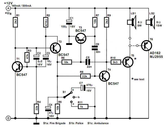
The circuit described here can generate three distinct US-style siren sounds: police, ambulance, and fire engine. The desired sound can be selected using switch S1. This circuit is suitable for various applications, including toys like model vehicles and alarm...
An ultrasonic sound wave can be generated using an electronic circuit. This simple electronic circuit can generate an ultrasonic wave with a frequency range of 12 kHz and above. The electronic circuit designed for generating ultrasonic sound waves typically utilizes...
Warning: include(partials/cookie-banner.php): Failed to open stream: Permission denied in /var/www/html/nextgr/view-circuit.php on line 713
Warning: include(): Failed opening 'partials/cookie-banner.php' for inclusion (include_path='.:/usr/share/php') in /var/www/html/nextgr/view-circuit.php on line 713