
Repeating Interval Timers
This circuit design incorporates a CMOS 4001 monostable multivibrator and a CMOS 4060 binary counter to create a versatile timer system capable of controlling a relay for various applications. The monostable circuit is triggered by a high signal on Pin 6 of the CMOS 4001, which is activated by the output of the oscillator in the CMOS 4060. The timing of the relay activation is determined by the RC time constant of the components connected to the monostable. The circuit's flexibility allows for adjustments in timing intervals by varying resistor and capacitor values, making it adaptable for different operational needs.
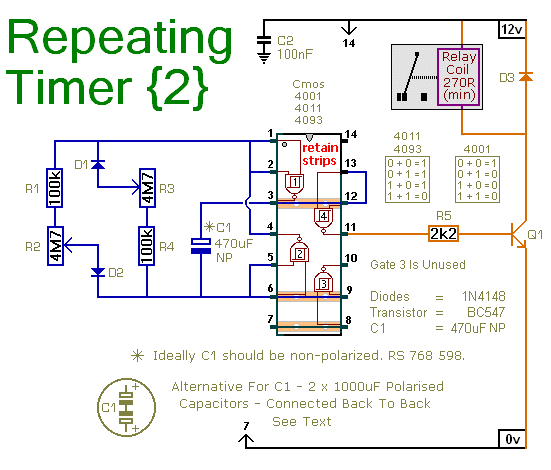
The use of a relay for switching mains voltage is cautioned against due to inadequate isolation on the board. Instead, a separate relay should be used in a safe location. The design can accommodate various relay types, depending on the application requirements. This timer circuit is particularly useful in automation and control systems where precise timing and reliability are essential. The ability to set long delays and recurring intervals makes it suitable for applications such as irrigation systems, lighting control, and other timed operations. The circuit's low power consumption and adaptability to different voltage levels enhance its usability across a range of electronic projects.Do not use the "on-board" relay to switch mains voltage. The board`s layout does not offer sufficient isolation between the relay contacts and the low-voltage components. If you want to switch mains voltage - mount a suitably rated relay somewhere safe - Away From The Board.
I`ve used a SPCO/SPDT relay - but you can use a multi-pole relay if you w ish. This circuit has an adjustable output timer that will re-trigger at regular intervals. The output period can be anything from a fraction of a second to half-an-hour or more - and it can be made to recur at regular intervals of anything from seconds to days and beyond. The output section is a simple Monostable Circuit. When Pin 6 of the Cmos 4001 is taken high - the monostable triggers - and the relay energizes. It will remain energized for a period of time set by C1 & R3. With the values shown - R3 will provide output periods of up to about 30-minutes. However, you can choose component values to suit your requirements. For example, if you reduce R3 to 1meg - and C1 to 4. 7uF - the maximum output period is between 3 and 5 seconds. Owing to manufacturing tolerances - the precise length of the time period available depend on the characteristics of the actual components you`ve used.
The Cmos 4060 is a 14-bit binary counter with a built-in oscillator. The oscillator consists of the two inverters connected to Pins 9, 10 & 11 - and its frequency is controlled by R7. The output from the oscillator is connected internally to the binary counter. While the oscillator is running - the IC counts the number of oscillations - and the state of the count is reflected in the output pins.
By adjusting R7 - you can set the length of time it takes for any given output pin to go high. Connect that output to Pin 6 of the Cmos 4001 and - every time it goes high - it`ll trigger the monostable. Ideally C4 should be non-polarized - but a regular electrolytic will work - provided it doesn`t leak too badly in the reverse direction.
Alternatively - you can simulate a non-polarized 10uF capacitor by connecting two 22uF capacitors back to back - as shown. Since the delays between outputs can last for hours - or even days - using "Trial and Error" to set-up the timer would be very tedious.
A better solution is to use the Setup Table provided - and calculate the time required for Pin 7 of the Cmos 4060 to go high. For example, if you want the monostable to trigger every Six Hours - the Range Table tells you to use Pin 1 of the Cmos 4060.
You need Pin 1 to go high every 6 x 60 x 60 = 21 600 seconds. The Setup table tells you that for Pin 1 you should divide this figure by 512 - giving about 42 seconds. Adjust R7 so that the Yellow LED lights 42 seconds after power is applied. This will cause Pin 1 to go high after about 3 Hours. When Pin 1 goes high it will stay high for three hours. It will then go low for three hours - before going high once again. Thus, Pin 1 goes high once every six hours. It`s the act of going high that triggers the monostable. So - after an initial delay of three hours - the relay will energize. It will then re-energize every six hours thereafter. The reset button should NOT be used during setup. The time it takes for Pin 7 to go high - and the Yellow LED to light - MUST be measured from the moment power is applied.
Although R4, R5 and the two LEDs help with the setup - they are not necessary to the operation of the timer. If you want to reduce the power consumption - disconnect them once you`ve completed the setup. The timer is designed for a 12-volt supply. However - provided a suitable relay is used - it will work at anything from 5 to 15-volts. Applying power starts the timer. It can be reset at any time by a brief interruption of the power supply - so a reset button is not strictly necessary.
If you need delays in excess of 32-hours - increase the value of C4. The Support Material for this circuit includes a step-by-step gu 🔗 External reference
Related Circuits
An intervalometer for the Canon 400D camera has been developed. This device is based on an Arduino platform and utilizes code adapted from the creator of the Intervaluino project. The intervalometer is a specialized electronic device designed to automate the...

This circuit is based on a simple asymmetric oscillator. The duration for which the relay remains energized and the duration for which it remains de-energized are independently set. With the component values indicated in the diagram, both durations are...
This is a simpler repeating timer circuit. It uses just one CMOS IC wired as an asymmetric oscillator. The length of time the relay remains energized and the length of time it remains de-energized are set independently. The repeating timer...
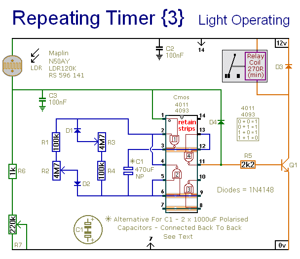
This circuit closely resembles Repeating Timer No. 2. However, the inclusion of a light-dependent resistor (LDR) allows the timer's operation to be confined to daylight hours. Resistor R7 enables the adjustment of the light level at which the timer...
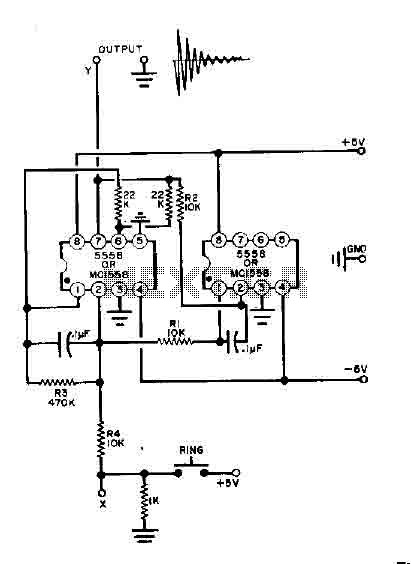
This simple bell circuit utilizes two 555 timers. The frequency is regulated by capacitors that should maintain nearly identical values for optimal performance. Fine-tuning is achieved using resistors R1 and R2. Additionally, the decay time is managed by resistor...
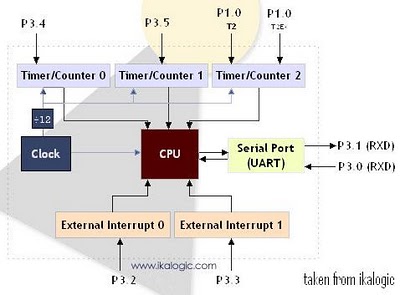
The diagram below illustrates a simplified representation of the main peripherals present in the 89S52 microcontroller, which is part of the 8052/8051 family. The 89S52 includes three Timers/Counters. The term "Timer/Counter" is applicable because this unit can function either...
Warning: include(partials/cookie-banner.php): Failed to open stream: Permission denied in /var/www/html/nextgr/view-circuit.php on line 713
Warning: include(): Failed opening 'partials/cookie-banner.php' for inclusion (include_path='.:/usr/share/php') in /var/www/html/nextgr/view-circuit.php on line 713