
mic preamplifier circuit based tlc251
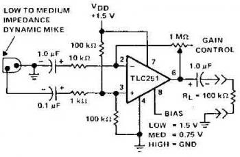
The microphone preamplifier circuit utilizing the TC251 operational amplifier is designed to enhance the signal from a microphone before it is processed by subsequent audio equipment. The TC251 is particularly advantageous in portable audio applications due to its low operating voltage and minimal current draw, which prolongs battery life.
The circuit's design includes a biasing network that ensures optimal performance across its specified frequency range, maintaining fidelity in sound reproduction. The frequency response of 27 Hz to 4.8 kHz is suitable for capturing the nuances of voice and instruments, making it effective for various audio applications, including recording and live sound reinforcement.
Incorporating a bias-select pin allows for flexibility in configuring the preamplifier to meet specific application requirements. By selecting different bias settings, the user can optimize the circuit for either lower power consumption or enhanced performance, depending on the needs of the application. This feature is particularly beneficial in scenarios where battery life is critical, allowing the designer to balance performance and efficiency.
The TC251's stability at unity gain ensures reliable operation in feedback configurations, which is essential for maintaining signal integrity in audio processing. Overall, the microphone preamplifier circuit based on the TC251 operational amplifier represents a robust solution for low-power, high-performance audio applications.Here the schematic diagram of mic preamplifier which build based on operational amplifier TC251. The TLC251 is operating in low bias. The circuit works with only 1. 5 V supply draws electric current of only 10 mA, so the battery operation will be prefered. Circuit frequency response is 3dB, 27 Hz to 4. 8 kHz. The TLC251 are low-cost, low-power progr ammable operational amplifiers designed to operate with single or dual power supplies. Because the input common-mode range extends to the negative rail and the power consumption is very low, this chip is ideally suited for battery-powered or energy-conserving applications. A bias-select pin can be used to program one of three ac performance and power-dissipation levels to suit the application.
The series features operation down to a 1. 4V supply and is stable at unity gain. 🔗 External reference
Related Circuits
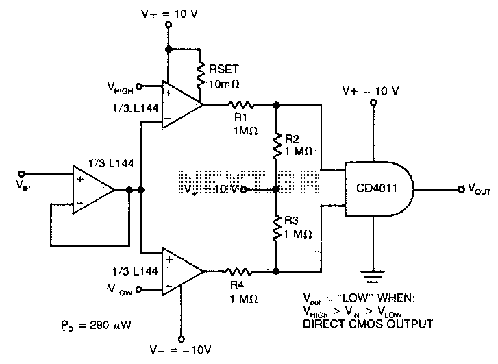
The detector utilizes three sections of an L144 and a DC4011 type CMOS NAND gate to create a very low power voltage monitor. If the input voltage, Vin, is above Vhigh or below Vlow, the output will be a...
This technique eliminates the need for an additional cable to power the FM antenna amplifier. The RF signal and the DC current that supplies the amplifier utilize the same cable simultaneously. An FM antenna booster circuit diagram can be...
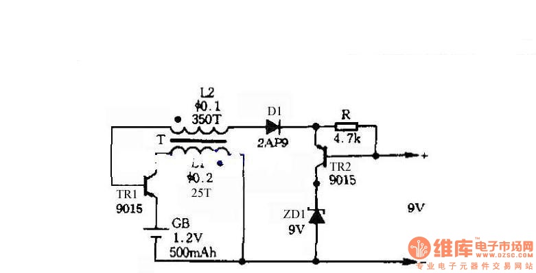
The circuit does not require a separate power switch or transformation to control the switches on the table. It offers advantages such as low power consumption, stability, reliability, and no impact on instrument accuracy. The transformer T in the...
The circuit design utilizes a VHF amplifier configured to operate within the frequency range of 88 to 108 MHz, specifically for Band 2 radio applications. The VHF amplifier circuit is designed to enhance weak radio frequency signals in the specified...
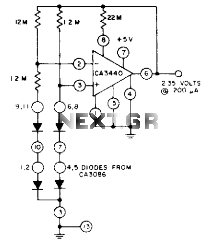
The circuit utilizes a CA3440 BiMOS operational amplifier and a CA3086 transistor array. The no-load current drawn from the 5-volt supply is 1.5 µA. The load current can reach up to 200 µA while still maintaining output voltage regulation...
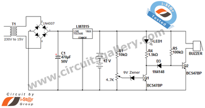
This is a straightforward 12V rechargeable smart battery charger circuit. It can be utilized as a charger for car batteries, inverter batteries, emergency light batteries, and more. An automatic indicator alarm circuit accompanies this battery charger schematic. The primary...
Warning: include(partials/cookie-banner.php): Failed to open stream: Permission denied in /var/www/html/nextgr/view-circuit.php on line 713
Warning: include(): Failed opening 'partials/cookie-banner.php' for inclusion (include_path='.:/usr/share/php') in /var/www/html/nextgr/view-circuit.php on line 713