
RF Preamplifier Operating in Band 2 VHF Range

The VHF amplifier circuit is designed to enhance weak radio frequency signals in the specified frequency band, which is commonly used for FM radio transmission. The amplifier typically consists of several key components, including transistors, resistors, capacitors, and possibly inductors, depending on the specific design requirements.
The transistors used in the amplifier are selected for their ability to operate efficiently at VHF frequencies. They may be configured in a common emitter or common collector arrangement to provide the desired gain while maintaining stability across the frequency range. Biasing resistors are employed to set the operating point of the transistors, ensuring linear amplification and minimizing distortion.
Capacitors are used for coupling and bypassing purposes. Coupling capacitors allow the AC signals to pass through while blocking DC components, and bypass capacitors help to stabilize the power supply by shunting high-frequency noise to ground. Inductors may be included in the design to form tuned circuits that enhance selectivity and improve the overall performance of the amplifier.
The circuit may also incorporate feedback mechanisms to enhance linearity and reduce gain variations due to temperature changes or component tolerances. The output stage of the amplifier is designed to match the impedance of the antenna or subsequent stages in the signal chain, ensuring maximum power transfer and minimizing signal loss.
Overall, the VHF amplifier circuit for Band 2 radio applications is a critical component in achieving clear and reliable radio signal reception and transmission within the designated frequency range. Proper design considerations, including component selection and circuit topology, are essential for optimizing performance and ensuring compliance with regulatory standards.The circuit design employs a VHF amplifier adjusted in such a way that it will operate in the frequency range of 88 to 108 MHz, as part of the Band 2 Radi.. 🔗 External reference
Related Circuits
This is a simple microphone preamplifier circuit designed for use between a microphone and a stereo amplifier. This circuit is compatible with standard home stereo amplifier line, CD, aux, and tape inputs. It can accept both dynamic and electret...
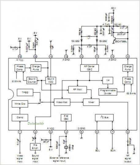
The TA1383AFG integrates an NTSC chroma decoder, a multi-point scan sync processor (equivalent to pin D4), and an H/V frequency counter in a 30-pin flat package. This integrated circuit (IC) is suitable for double scan televisions manufactured by Toshiba...
There are two types of preamplifiers for magnetic phono cartridges. The most common type includes an RIAA equalization network in the feedback loop, as described in the March 2002 issue of SILICON CHIP. The second type, previously used in...
Soundblaster soundcard series (SB16, SB32, AWE32 and AWE64) have all a microphone input designed to be used with the electret microphones which come with the soundcard package (some packages) or with separate microphone designed to be used with SoundBlaster...
This complete high quality, low noise 5-BAND GRAPHIC EQUALIZER circuit is based around Monolithic Linear integrated circuit LA3600 manufactured by SANYO. This circuit is very easy to build and has good Quality. You can use it with Portable component...
This module utilizes an unconventional topology while retaining the fundamental operational amplifier circuitry of the main module, with some modifications in resistor values. A distinctive feature of this circuit is the incorporation of six-way switches instead of the more...