
Micro Power AM Broadcast Transmitter

The circuit employs the 74HC14, which is a high-speed CMOS hex inverter featuring Schmitt trigger inputs. This component is ideal for generating square wave signals due to its hysteresis characteristics, which provide clean transitions between high and low states, minimizing noise and ensuring stable oscillation.
In the VFO configuration, the 100pF capacitor is connected in parallel with a resistor, forming an RC timing circuit that determines the frequency of oscillation. The frequency can be calculated using the formula f = 1 / (2 * π * R * C), where R is the resistance and C is the capacitance. By varying the resistance, the frequency output can be adjusted to meet specific application requirements.
The output from the 74HC14 is connected to the base of a small signal transistor, which operates in class C mode. In this configuration, the transistor conducts for less than half of the input signal cycle, allowing it to amplify high-frequency signals efficiently. Class C amplifiers are known for their high efficiency, making them suitable for RF applications.
The transistor's collector is connected to a load, which could be an antenna or another stage of amplification. Proper biasing must be applied to the transistor to ensure it operates within the desired parameters. This circuit can be used in various applications, including RF transmitters, signal generators, and other electronic devices requiring square wave oscillation and amplification. Proper layout and component selection are essential to ensure reliable operation and minimize distortion in the output signal.In this circuit, a 74HC14 hex Schmitt trigger inverter is used as a square wave oscillator to drive a small signal transistor in a class C amplifier configuration. The oscillator frequency can be either fixed by a crystal or made adjustable (VFO) with a capacitor/resistor combination.
A 100pF capacitor is used in place of the crystal for VFO operation. Amp.. 🔗 External reference
Related Circuits
%2BCircuit%2Bdiagram%2Busing%2BCD4047%2Band%2BIRFZ44%2Bpower%2BMOSFET.png)
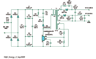
This simple low-power DC to AC inverter circuit converts 12V DC to either 230V or 110V AC. By making simple modifications, it is also possible to convert 6V DC to 230V AC or 110V AC. This inverter can be...
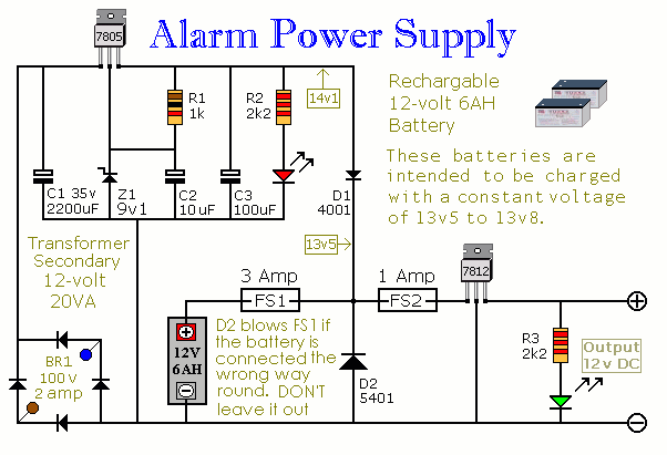
This Power Supply is suitable for the Modular Burglar Alarm. However, it has other applications. It is designed to provide an output of 12-volts, with a current of up to 1-amp. In the event of mains failure, the back-up...
As electric utility companies face the challenge of reducing greenhouse gas emissions and managing rising costs and lead times for new generating capacity, they are adopting the concept of the smart grid. A key component of the smart grid...
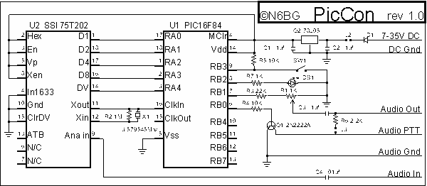
PicCon is a PIC microcontroller based radio controller designed for hidden transmitter hunting. When combined with a radio transmitter, it will produce tone sequences and Morse code messages at user-programmed times. It is completely field programmable via DTMF tones,...
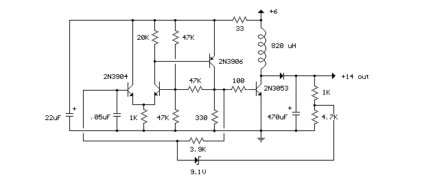
This compact switching power supply utilizes a Schmitt trigger oscillator to control a switching transistor, which provides current to a small inductor. When the transistor is activated, energy accumulates in the inductor, and this energy is subsequently released into...
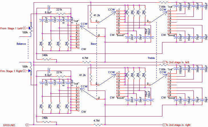
The primary amplifying stages consist of triode-connected 6088 tubes. As previously mentioned, there are two amplifying stages, which provide a non-inverted input to output connection and sufficient gain to include tone control. The tone controls are switch-selected, allowing a...