
Battery powered buffer amplifier

The circuit design incorporates a voltage monitoring mechanism that continuously assesses the supply voltage levels. When the voltage falls below a predefined threshold, the circuit activates a disconnect feature to safeguard the cell from potential damage due to under-voltage conditions. This is particularly crucial in battery management systems where maintaining the integrity of the cell is paramount.
In the event of an output overload, the circuit also triggers the disconnect functionality. This overload detection is typically implemented using a current sensing resistor in series with the load, allowing the circuit to monitor the current flowing through. If the sensed current exceeds a specified limit, the disconnect circuitry engages, effectively isolating the cell from the load.
The indicator diode serves a dual purpose within the circuit. It provides a visual indication of the circuit's operational status. When the disconnect circuitry is activated, the diode extinguishes, signaling that the cell is no longer connected to the load. This feature is beneficial for user feedback, allowing for immediate recognition of the circuit's state without the need for additional monitoring equipment.
Overall, this circuit design prioritizes the protection of the power source while providing clear operational feedback through the indicator diode, ensuring both reliability and user awareness in various operational scenarios.This circuit has negligible loading and disconnects the cell for low supply voltage or overload on output. The indicator diode extinguishes as disconnect circuitry is activated.
Related Circuits
A wideband transmission or communication channel consists of a broader bandwidth than a single voice channel, utilizing a carrier wave of a specific modulated frequency. This allows for the transmission of more information than narrowband systems, but less than...
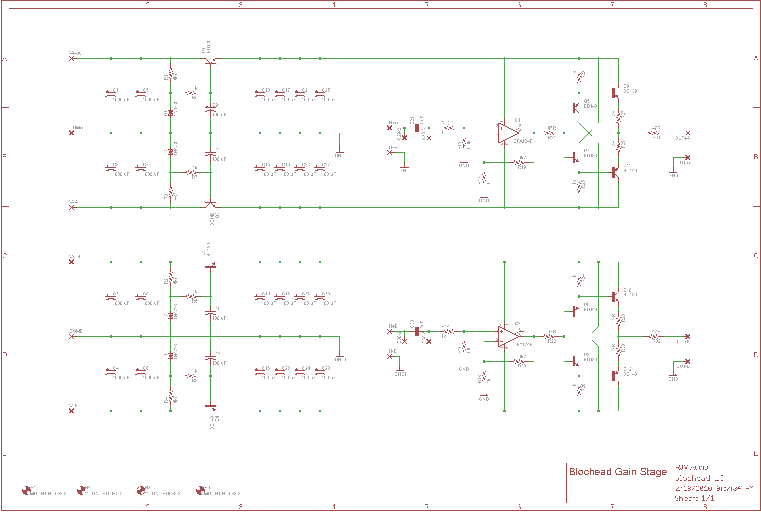
The circuit is intended to operate with a 100k volume potentiometer and can function as either a line stage or a headphone amplifier. It features a standard non-inverting gain stage with a gain of 15 dB, followed by a...
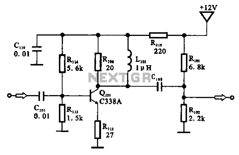
The amplifier circuit is designed as a pre-amplifier configuration. It utilizes transistor Q101 and other components such as inductor L101 and biasing elements. The transistor operates as a common emitter intermediate frequency (IF) amplifier. The IF signal is coupled...
Designs for audio amplifiers with DC coupling to the load are not frequently seen today, despite offering distinct advantages. Audio amplifiers that employ DC coupling to the load provide several benefits that can enhance performance in specific applications. In traditional...
Construct a basic audio amplifier utilizing transistors. While integrated circuit (IC) designs are available for this purpose, the intention is to use transistors to gain practical knowledge about their amplification capabilities. The article "Amplifier Basics - How Amps Work...
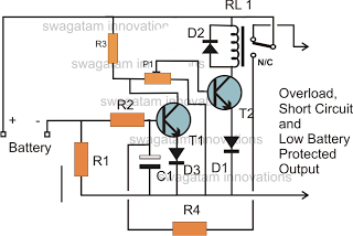
The battery voltage must pass through resistor R1 before reaching the output load. As a result, the current flowing through R1 is proportionately transformed into a voltage across it. When the battery voltage drops below a certain threshold, the...