
Most Popular Circuits
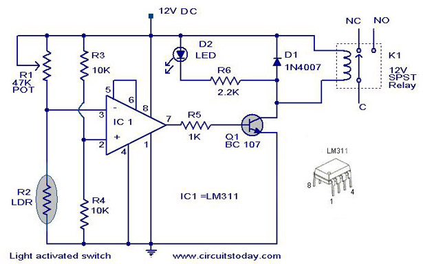
The light-activated switch operates by comparing the voltage across the LDR with the fixed reference voltage. When the ambient light level decreases, the voltage across the LDR rises above the reference voltage, causing the output of the comparator to change state. This output can be used to control a relay or another switching device, allowing the circuit to turn on or off connected appliances based on the presence or absence of light.
The circuit's design is straightforward, making it suitable for applications such as automatic lighting systems or security lighting. The use of the LM311 comparator ensures precise voltage comparison, while the LDR provides a simple and effective means of detecting light levels. The resistors R3 and R4 can be adjusted to set the threshold for light activation, allowing for customization based on specific requirements. Overall, this circuit offers a reliable solution for light-activated switching applications.
The light-activated switch employs a straightforward voltage comparator configuration, leveraging the characteristics of the LM311 IC and an LDR. The reference voltage is established at 6V using a voltage divider formed by resistors R3 and R4. The LDR's resistance is inversely related to the light intensity; hence, in low-light conditions, the resistance is high, resulting in a higher voltage across the LDR.
The circuit's operation hinges on the comparator's function, where the non-inverting input is constantly supplied with the reference voltage, while the inverting input varies based on the LDR's resistance. When light levels drop, the voltage at the inverting input exceeds the reference voltage, prompting the comparator to trigger a change at its output. This output can control various devices, such as relays or transistors, effectively enabling or disabling connected loads based on ambient light conditions.
This configuration is particularly advantageous for applications requiring automatic control of lighting systems, such as outdoor lights that activate at dusk or security lights that respond to changes in light levels. The LM311's precision and the simplicity of the LDR make this circuit an excellent choice for hobbyists and professionals seeking a reliable light-activated switch solution. Adjustments can be made to the resistor values to fine-tune sensitivity, ensuring optimal performance in varying light environments.A Simple Light activated switch This is the circuit diagram of a light activated switch based on National Semiconductors comparator IC LM 311 and a LDR. The circuit is based on a voltage comparator circuit wired around IC 1. The non inverting in put of IC1 is given with a reference voltage of 6V using resistors R3 and R4. The input to the inverting input will be the voltage across the LDR that is light dependent. At darkness the resistance of the LDR will be high and so do the voltage across it. At this condition the voltage at the Simple AM Transmitter Description Here is the circuit diagram of a simple AM transmitter circuit that can transmit your audios to your backyard. This circuit is designed with limited power output to match the FCC regulations and still produces enough amplitude modulation of voice in the medium wave band to satisfy your personal needs.
You will love this!. The circuit has two parts, an audio amplifier and a radio frequency oscillator. The oscillator is built around Q1 (BC109) and related components. The tank circuit with inductance L1 and capacitance VC1 is tunable in the range of 500kHz to 1600KHz. These components Low Cost 150 Watt Amplifier Circuit Description This is the cheapest 150 Watt amplifier circuit you can make, I think.
Based on two Darlington power transistors TIP 142 and TIP 147, this circuit can deliver a blasting 150 W Rms to a 4 Ohm speaker. Enough for you to get rocked ;then try out this. TIP 147 and 142 are complementary Darlington pair transistors which can handle 5 A current and 100V, famous for their ruggedness.
Here two BC 558 transistors Q5 and Q4 are wired as pre amplifier and TIP 142, TIP 147 together with TIP41 (Q1, Q2, Q3) is used for driving the speaker. This 100 Watt Inverter Description Here is a 100 Watt inverter circuit using minimum number of components.
I think it is quite difficult to make a decent one like this with further less components. Here we use CD 4047 IC from Texas Instruments for generating the 100 Hz pulses and four 2N3055 transistors for driving the load. The IC1 Cd4047 wired as an astable multivibrator produces two 180 degree out of phase 100 Hz pulse trains.
These pulse trains are preamplifed by the two TIP122 transistors. The outputs of the TIP 122 transistors are amplified by four 2N 3055 transistors (two transistors for each half Remote control tester This is a simple remote controller tester circuit based on infrared sensor IC TSOP 1738. When the IR waves fall on the sensor it output changes to low state. This makes the transistor Q1 ON and LED will blink according to the code contained in the signal. So for press of each button the LED blinks in different ways. This is a good indication of the working of remote. The diode D1drops 0. 7 V to give the IC ~ 5V supply from the available 6V. R2 is a current limiting resistance. Get a better understanding on the Remote controlled switch for Appliance Here is a versatile remote controlled switch that can ON or OFF any appliance connected to it using a TV remote.
IR remote sensor IC TSOP 1738 is used for receiving the signal. Normally when no signal is falling on IC3 the output of it will be high. This makes Q1 OFF. When a signal of 38 KHz from the TV remote falls on the IC3 its output goes low. This makes Q1 conduct and a negative pulse is obtained at pin 2 of IC 1 NE 555. Due to this IC1 wired as a monostable Function Generator Circuit The ICL8038 is a function generator chip, capable of generating triangular, square, sine, pulse and sawtooth waveforms. From these sine, square & triangular wave forms can be made simultaneously. There is an option to control the parameters like frequency, duty cycle and distortion of these functions.
This is the best function generator circuit for a beginner to start with and is of course a must on the work bench of an electronics hobbyist. The circuit here is designed to produce waveforms from 2 🔗 External reference
Related Circuits
This circuit illustrates the use of the LM319 integrated circuit in a thermostat circuit diagram. Features include a 2-watt potentiometer for triac power control and a 10 Megaohm resistor. The LM319 is a dual comparator IC that is commonly used...

This open-source thread focuses on the development of a "MOSFET Heating Circuit," which is a modified version of an existing design. The MOSFET Heating Circuit is designed to efficiently manage and control heating elements using MOSFET technology. MOSFETs (Metal-Oxide-Semiconductor Field-Effect...

This is a brief jam session to explore the capabilities of a recently completed step sequencer. This device is quite enjoyable and expands creative possibilities. A detailed post with the circuit and instructions for building it will be provided...

Commercial FM demodulation occurs at an intermediate frequency (IF) of 10.7 MHz. With a frequency deviation of ±75 kHz, the deviation of the IF carrier is approximately ±0.7%. This deviation allows for the conversion of FM to AM or...
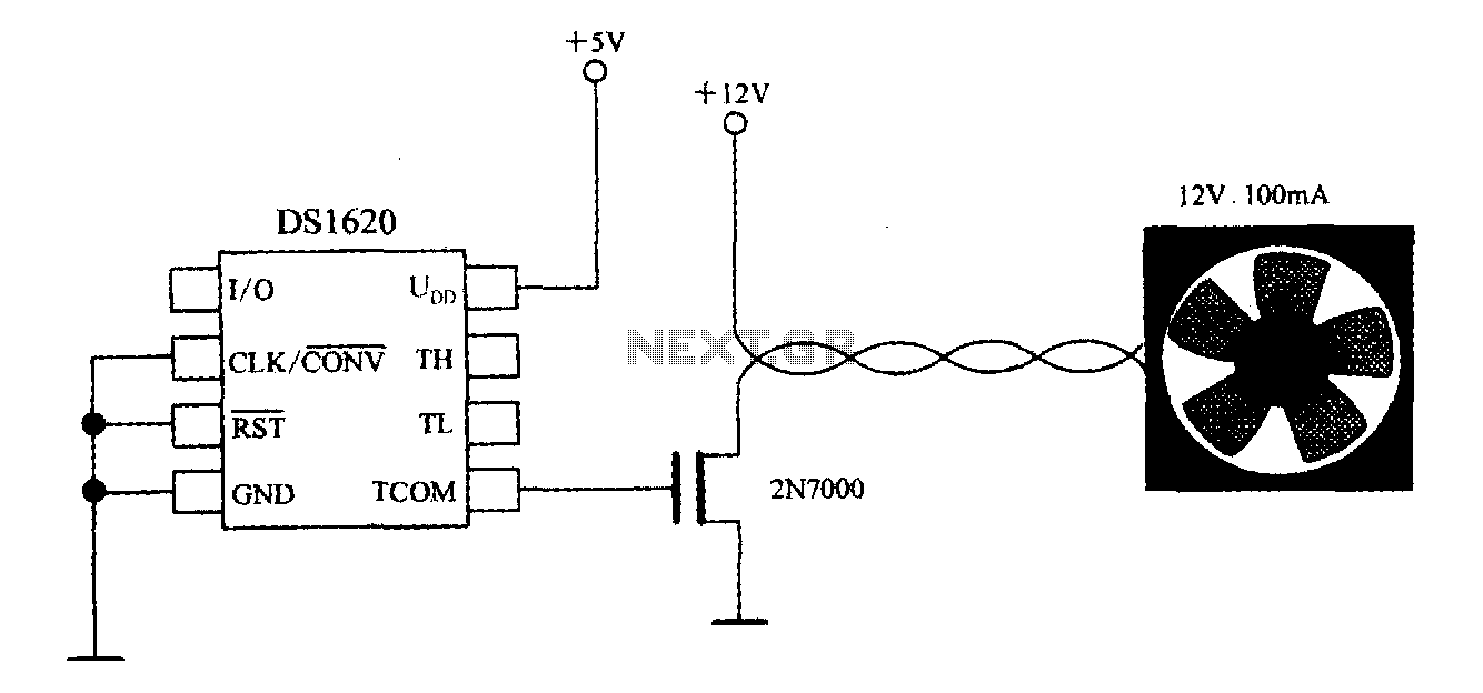
The DS1620, in conjunction with a microprocessor, is utilized to monitor temperature. By controlling the fan, the thermal conditions of the chip can be adjusted to establish a temperature control circuit as illustrated in the accompanying figure. The system...
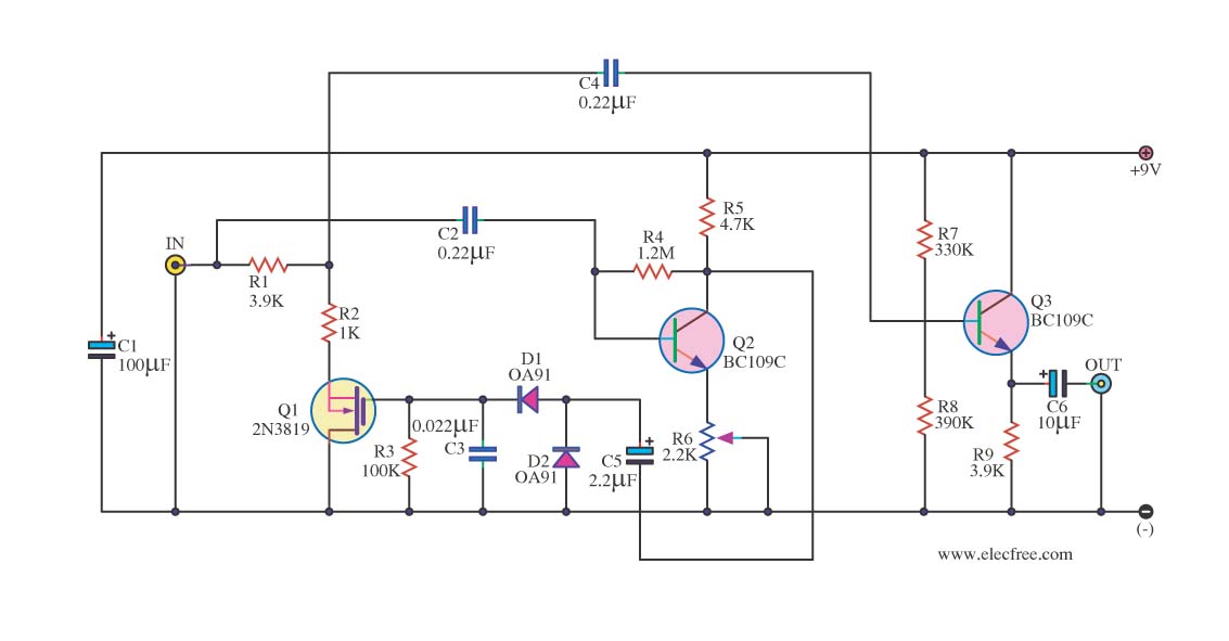
In audio systems, noise signals are generally undesirable, and efforts are often made to eliminate them. Transistors can be utilized effectively for this purpose due to their availability and low noise characteristics. The following circuit serves as a Noise...