
three digit display.
The DVM-module is designed to offer flexibility and precision in voltage and current measurements, making it suitable for various applications in electronics. The firmware control allows for customization, enabling users to adjust settings according to specific needs. The use of operational amplifiers like the TS272 or TLC272 ensures high input impedance, which is crucial for accurate measurement, particularly in sensitive applications like electrochemical measurements.
The module's capability to measure both voltage and current through low-ohm resistors further enhances its functionality. The calibration process via the VDIV adjustment in the firmware is essential for ensuring the accuracy of measurements, particularly when dealing with small voltage drops in current measurements.
The integration of a counting mechanism using light beams expands the module's versatility, allowing for non-contact object counting. This feature is particularly useful in automation and monitoring applications. The addition of a photodiode with a laser pointer or infrared LED provides a reliable method for counting over varying distances, making it adaptable to different operational environments.
Furthermore, the incorporation of a digital temperature sensor like the DS18S20 adds another layer of functionality, enabling temperature monitoring alongside voltage and current measurements. This multifunctionality positions the DVM-module as a comprehensive tool for electronics testing and monitoring, suitable for both hobbyists and professionals in the field.The Mini 3 digit display aka "DVM-module" (digital voltmeter module) can easily be tuned and modified because you have control over the firmware. The key advantages of this module are: The internal reference voltage in the atmega8 microcontroller is 2.
56V. Just by adding 2 resistors one can measure any voltage higher than 2. 56V. How can I measure smaller voltages It`s simple: just add an amplifier. The problem is only the power of supply for the amplifier circuit. A lot operational amplifiers need positive and negative voltages of e. g +/- 15V. That is not really convenient for our application. We need something that works with about 5V (same as the atmega8). The TS272 or TLC272 is a very good option. It has a very high input impedance of typically 1GOhm. You can use this therefore for true voltage measurements e. g on electrochemical cells. The combination of resistors in the above example gives you a measurement range from 0-500mV with 1mV resolution. VDIV has to be adjusted in the file analog. c to calibrate the amplification factor into the software: Note that a voltmeter with more than 1GOhm input impedance is very sensitive to electric fields and grabs any voltage just out of the air.
I recommend to use a shielded cable or to lower the input impedance by adding a resistor in parallel to the input (Ri in the above schematic). To measure a current you just need to measure the voltage over a low ohm resistor (e. g 1 Ohm, 5W). A current of 2A would then result in a voltage drop of 2V. By changing the VDIV calibration constant in the file analog. c you can calibrate the circuit as needed. If a voltage drop of 2V is not acceptable then just use 0. 1 Ohm and add an amplifier. You can then adjust it to your needs by using the above amplifier circuit with a different amplification factor (resistors R1, R5 and R2).
The DVM module measures always voltages between GND and the ADC0 pin on the atmega8 microcontroller. This means that the low ohm resistor needs to be connected on one side to GND. So far we have use mostly the analog to digital conversion capability of the atmega8 microcontroller. This microcontroller has however also digital input lines. Here is a little counter: The counter does not have to be connected to a mechanical switch. It can also be connected to a "light beam" and count objects interrupting that beam. For this we add a photodiode and a transistor which acts as amplifier. A small laser pointer pen makes a very good light beam and works even over long distances. You do not have to power the laser-pointer from a battery. Just open it take out the battery and connect it to a DC power supply. You can power it from the same 5V that the counter circuit is powered from. In this case you need to add a resistor in series with the laser pointer. A laser pointer that used 2x1. 5V batteries will probably need a 220 Ohm resistor in series when connected to 5V. Photodiodes are most sensitive to infrared light. A laser pointer is the best light source for long distances (1m to 200m). For shorter distances you can also use an Infrared-LED (invisible to humans). This application is quite similar to the counter except that we generate the pulses via the atmega8 internal clock.
The circuit has no crystal but uses the internal clock. This internal clock is not calibrated but you can calibrate the timer by adjusting the line The circuit has several inputs to start and stop the timer as well as a button to reset it. You can use a button connected to pin PB1. Clicking once starts the timer and clicking a second time stops it. You can use the individual start stop input lines or buttons. The ds18s20 from maxim dallas semiconductors is a calibrated digital temperature sensor. It looks like a small transistor. The pinout description is shown on the right. We connect it to this "Mini 3 digit display" and we have a very reliable and accurate digital thermometer.
This therm 🔗 External reference
Related Circuits
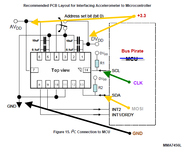
The Bus Pirate is an effective tool for exploring new chips with a PC, eliminating the need for integration into a microcontroller project. Upon receiving the unit, testing it with the MMA7456L accelerometer featuring an I2C/SPI interface from Freescale...
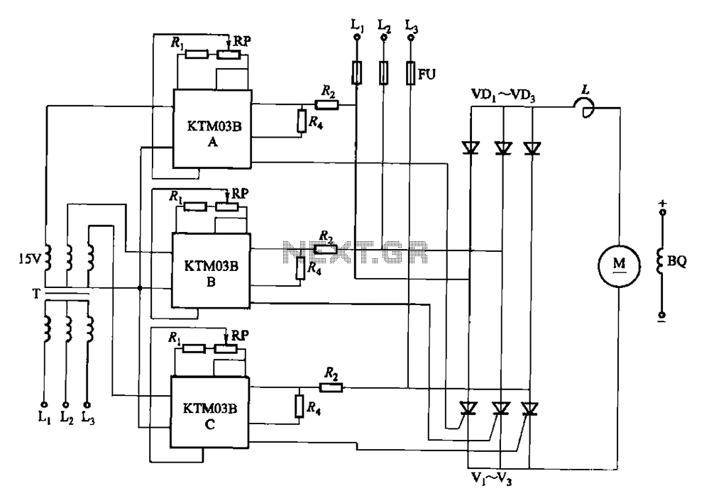
Adjusting the phase potentiometer RP can change the conduction angle of each corresponding thyristor (V1-V). This adjustment alters the voltage applied across the load. The circuit utilizes a phase control technique to manage the power delivered to a load by...
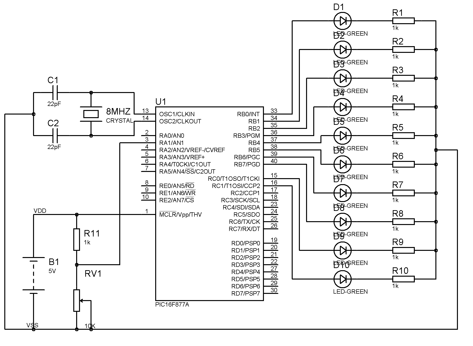
The result displayed on the LCD is incorrect; the thermometer shows a reading of 414 degrees instead of the actual room temperature. Assistance is needed to determine whether the issue lies within the hex file or the sensor itself....
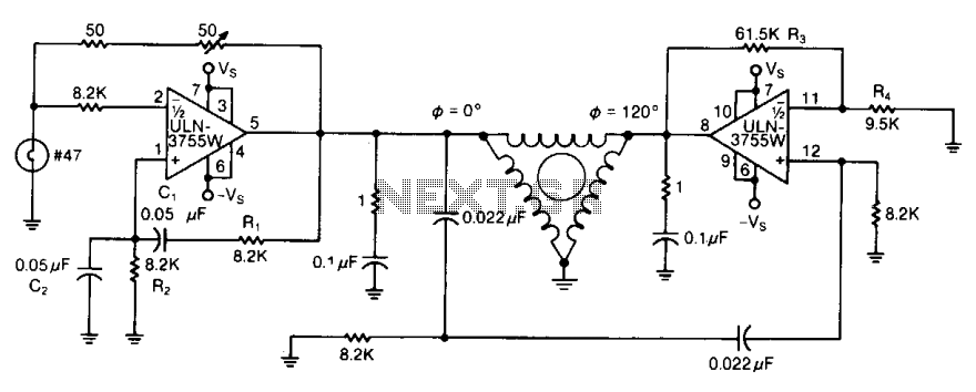
By varying either R1 or R2, the oscillator frequency can be adjusted over a narrow range. The R3/R4 ratio sets the second amplifier's gain to compensate for signal attenuation occurring in the phase shifters. The circuits can be driven...
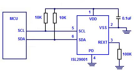
The Intersil ISL29001 is a digital light sensor designed to measure light intensity and easily interface with a microcontroller. The Intersil ISL29001 is a highly integrated digital light sensor that operates using a photodiode and an analog-to-digital converter (ADC) to...
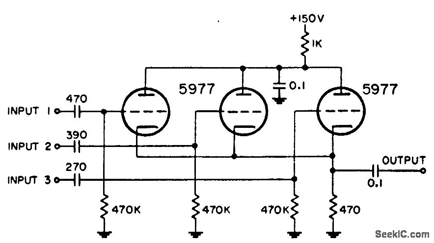
Utilized in radar systems for the integration of any three of the following components: radar video, beacon, range markers, range strobe, and azimuth markers. -NBS, "Handbook Preferred Circuits Navy Aeronautical Electronic Equipment," Vol. 1, Electron Tube Circuits, 1963, p...